3D Surface Layer Mesh Properties
To edit a 3D surface map, click once on the surface map to select it. The properties for the surface map are displayed in the Properties window. The 3D surface Mesh page is used to add mesh lines to the surface of the map. Mesh lines can be used to simulate a wireframe.
|
|
|
Change mesh properties in the Properties window on the Mesh page. |
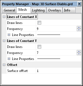
Lines of Constant X
Check the Draw lines box under the Lines of Constant X to draw lines along the surface at constant X values.
Frequency
You can change the frequency of the X lines by entering a new number into the Frequency box. If this value is one, every grid node in the X direction will have a mesh line. If this value is two, every other grid node in the X direction will have a mesh line. If this value is three, every third grid node in the X direction will have a mesh line, and so on.
Line Properties
Click the ![]() next to the Line Properties to open the line properties section for the X direction mesh lines. Line style, color, opacity, and width can be altered. 3D surface map mesh lines do not support complex line styles.
next to the Line Properties to open the line properties section for the X direction mesh lines. Line style, color, opacity, and width can be altered. 3D surface map mesh lines do not support complex line styles.
Lines of Constant Y
Check the Draw lines box under the Lines of Constant Y to draw lines along the surface at constant Y values.
Frequency
You can change the frequency of the Y lines by entering a new number into the Frequency box. If this value is one, every grid node in the Y direction will have a mesh line. If this value is two, every other grid node in the Y direction will have a mesh line. If this value is three, every third grid node in the Y direction will have a mesh line, and so on.
Line Properties
Click the ![]() next to the Line Properties to open the line properties section for the Y direction mesh lines. Line style, color, opacity, and width can be altered. 3D surface map mesh lines do not support complex line styles.
next to the Line Properties to open the line properties section for the Y direction mesh lines. Line style, color, opacity, and width can be altered. 3D surface map mesh lines do not support complex line styles.
Surface Offset
If you overlay two or more 3D surface maps, the mesh lines may appear dashed or broken. Experiment with the Surface offset values to change the distance between where the surface and mesh lines are drawn. The value is not associated with map units, instead it is offset by a factor. It is recommended that small changes be made to the Surface offset when trying to make the lines more clear.
Mesh Tips
- The default line frequency is one line in each direction.
- The mesh offset value o is calculated by:
o = (m)(factor)+r
where,
m = maximum depth slope of the polygon
factor = user-specified value in Surface offset, values typically range from 0.0 to 5.0
r = the smallest value guaranteed to produce a resolvable difference in window coordinate depth values (a constant)
To Draw Mesh Lines
- Click on the surface map to select it.
- In the Properties window, click on the Mesh tab.
- Check the Draw lines boxes in the Lines of Constant X and Lines of Constant Y sections.
- Change the Line Properties for the X and Y lines.
- You can change the frequency of the lines by entering a new number into the Frequency boxes.
- If you overlay two or more surface maps, the mesh lines may appear dashed or broken. Experiment with the Surface offset values to change the distance above the surface that the mesh is drawn.