2-Grid Vector Map Data Properties
To edit a 2-grid vector map, click once on the vector map to select it. The properties for the vector map are displayed in the Properties window. The vector map Data page contains the following options:
|
|
|
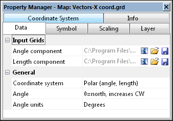
Specify the Coordinate System, Angle, Units, and two grid files on the Data page for a 2-grid polar vector map. |
|
|
|
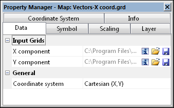
Specify the X component and Y component on the Data page for a 2-grid Cartesian vector map. |
Input Grid Files
The Input Grid section displays the path and file name for the grid files used for the map. If the entire file name is not shown, place the mouse over the file name. A small window will appear with the full path and name displayed.
For a Polar (angle, length) 2-grid vector map, the grids contain Angle component and Length component grids. The Angle component grid contains direction information. The vector at each grid node will be pointed in the direction of the Angle component. The Length component grid contains the length of the vector. The vector at each grid node will be as long as the value in the Length component.
For a Cartesian (X, Y) 2-grid vector map, the grids contain X component and Y component grids. The X component grid contains the length of the vector in the X direction. The Y component grid contains the length of the vector in the Y direction. The direction of each vector will be found by adding the two grid files. The magnitude is found using the Pythagorean theorem.
Grid Information
The ![]() button displays information about the grid file used to produce the map layer. The information includes the grid size, the minimum and maximum X, Y, Z, and C values contained in the grid file, and statistics. If the grid file contains more than 40 million nodes, you are asked if you wish to create a detailed report or a quick report. Click Yes in the message to create a detailed grid report, or click No to create a shorter quick grid report.
button displays information about the grid file used to produce the map layer. The information includes the grid size, the minimum and maximum X, Y, Z, and C values contained in the grid file, and statistics. If the grid file contains more than 40 million nodes, you are asked if you wish to create a detailed report or a quick report. Click Yes in the message to create a detailed grid report, or click No to create a shorter quick grid report.
Change File
Click the  button to display the Open Grid dialog. This allows a new or updated grid file to be specified for the 2-grid vector map. Select the new grid file and click Open to reference the new file.
Coordinate System Note
Regardless of the file selected with either the File | Reload Map Data command or by clicking the button in the Properties window, the coordinate system for the original map layer is used after updating the file. If this is not the correct coordinate system, click on the map layer to select it. In the Properties window, click on the Coordinate System tab and set the coordinate system to the appropriate new system.
Save File
Click the  button to display the Save Grid As dialog. This allows the grid file used for the 2-grid vector map to be saved to a new name. Set the File name, Save as type, and click Save to save the file. If a coordinate system has been defined on the Coordinate System tab in the Properties window, the Export Options dialog appears. Check the desired file formats. It is recommend that GS Reference (Version 2) file option be checked to generate a .GSR2 file. Click OK and the file is saved.
Coordinate System
Cartesian (X, Y) or Polar (Angle, Length) can be used in a two-grid vector map. To change the type of 2-grid vector map, click on the existing Coordinate System and select the desired coordinate system from the list. The Cartesian (X, Y) coordinate system requires one grid file with X magnitude components and the second grid file with Y magnitude components. The Polar (Angle, Length) coordinate option requires one grid with angle (direction) information and the second grid with length (magnitude) direction for the vectors. The Length Component Grid File cannot contain negative values.
Angle
When working with polar coordinates, set the location of the zero value to the north or east in the Angle option. Setting Angle to 0=north, increases CW, creates a polar system with increasing angles as shown in the left image below. Setting Angle to 0=eash, increases CCW, creates a polar system with increasing angles as shown in the right image below.
|
|
|
This image shows the two coordinate Angle orientations. In the image on the left, zero = North. Numbers increase clockwise. In the image on the right, zero = East. Numbers increase counter-clockwise. |

Angle Units
When working with polar coordinates,you can set the type of angle units used in the grid file. Set the Angle units to either Degrees or Radians . This is the unit of the data in the Angle component grid.