Image Slice
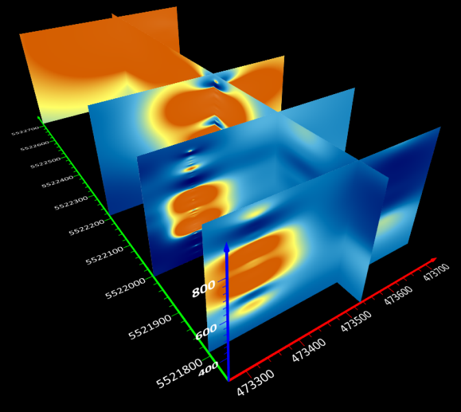
An image slice creates a planar image of the 3D grid at the specified position and rotation. Multiple image planes can be used to create a fence diagram.
Select a 3D grid volume in the Contents window and click 3D View | Tools | Add to 3D Grid | Image Slice to create an image slice.
|
| An image slice creates a planar image of the 3D grid in the 3D view. When combined the slices form a fence diagram. |
Image Slice Properties
|
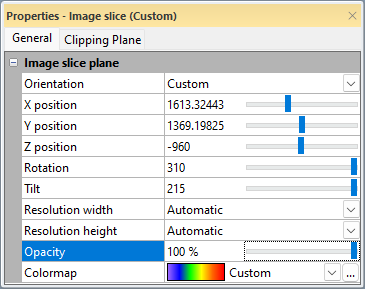
| Set the image plane position and appearance in the Properties window. |
Orientation
Select XY, XZ, or YZ in the Orientation field to quickly set the image slice orientation to one of the axis planes. Otherwise, select Custom to fully define the image slice position and orientation.
Position
The X/Y/Z position properties control the position of the image slice. Type coordinate values or use the slider to set the image slice position. Only one position property is displayed when an axis plane is used. All three coordinate positions are available when a Custom orientation is used.
Rotation and Tilt
When using a Custom orientation, you can modify the Rotation and Tilt properties.
- Positive Rotation values move the plane counterclockwise about the Z axis. Tilt must be greater than or less than zero for Rotation to affect the image slice.
- Positive Tilt values move the plane clockwise about the Y axis.
- When Rotation and Tilt are both equal to zero, the orientation matches the XY plane.
- When Rotation and Tilt both equal to 90, the orientation matches the XZ plane.
- When Rotation is equal to 0 and Tilt is equal to 90, the orientation matches the YZ plane.
Resolution
The Resolution width and Resolution height properties control the appearance of the image slice by determining the total number of pixels used to display the slice. The Resolution width is the number of pixels used to render the image slice along one side. The Resolution height is the number of pixels used to render the image slice along the adjacent side. The directions of the Resolution width and Resolution height vary depending on the shape and angle of the intersection with the 3D volume.
The Resolution width and Resolution height can be specified independently to account for different image slices. For image slices that are generally square, the Resolution width and Resolution height should be set to the same value. For image slices that are rectangular, i.e. one side is significantly longer than the other, the texture appearance may be improved by increasing the resolution along the long side of the image slice.
By default the Resolution width and Resolution height are set to automatic. When both Resolution width and Resolution height are set to Automatic, the image slice resolution along the longer direction is set to 1024 and the image slice resolution along the shorter side is set based on the ratio between the image width and height. For example, a square image will have 1024 pixels along the width and height while a long and skinny image may only use 256 pixels along the shorter direction. When only one of the Resolution width or Resolution height values are set to Automatic, the Automatic value varies based on the specified value and the ratio between the surface width and height.
Opacity
The Opacity property sets the opacity for the entire image slice. 100% is fully opaque. 0% is fully transparent. Overall opacity can also vary due to the specified Colormap. For example, if the Colormap uses a 0 to 100% ramp and the Opacity property is set to 50%, the image slice will appear to ramp from 0% to 50% opaque.
Colormap
Specify the colormap for the image slice in the Colormap field. Select a predefined colormap from the list or click the  button to modify the colormap in the Colormap Editor. The image slice is created using the same colormap as the Volume Render by default.
Interpolation
The Interpolation property controls how colors are rendered between 3D grid nodes on the image slice. This is particularly useful when visualizing categorical data, such as lithology codes.
-
Tri-linear: This is the default setting. It creates a smooth, blended transition between grid nodes. Use this for continuous data like temperature or concentration.
-
Nearest neighbor: This method colors the slice using the data point closest to each pixel without any interpolation. This is ideal for discrete data (e.g., geology units) to prevent the "bleeding" of colors or the creation of false intervening values between non-consecutive numeric codes.
|
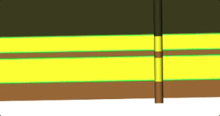
Tri-linear |
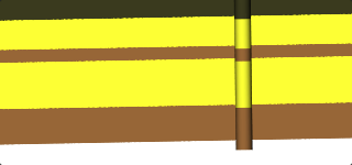
Nearest neighbor |
|---|---|
|
|
|
Note the interpolated Green bar between the Yellow and Brown. |
Data goes straight from Yellow to Brown, without interpolating Green between. |
Save
-
Save slice grid: Opens the Open Grid As window.
-
Save slice image: Opens the Export Image window.
Saving and Exporting Slice Images
Individual image slices and contour slices can be exported as standalone image files (e.g., .PNG, .TIF). This is particularly useful for generating flat cross-sections or profile views from a 3D volume.
Accessing the Save Command
The Save Slice Image command can be accessed via the following methods:
-
Ribbon: Select the slice, then click the 3D View | 3D Grid | Save Slice Image button.
-
Context Menu: Right-click the slice in the Contents window or the View window.
-
Properties: Click the Save Slice Image button on the General page in the Properties window.
Export Orientation and Geometry
When a slice is exported, Surfer flattens the 3D geometry into a 2D image based on the slice orientation:
|
Orientation |
Image X-Axis |
Image Y-Axis |
|---|---|---|
|
XY Plane |
Map X (Easting) |
Map Y (Northing) |
|
XZ Plane |
Map X (Easting) |
Map Z (Elevation) |
|
YZ Plane |
Map Y (Northing) |
Map Z (Elevation) |
|
Path Slice |
Distance along the path |
Map Z (Elevation) |
|
Custom |
Horizontal (along the lowest edge) |
Perpendicular "Up" from the X-axis |
Golden Nugget : Exported images are not georeferenced. Portions of the slice not visible in the 3D view (e.g., areas outside the grid limits or unfilled contour regions) are exported as transparent pixels, provided the chosen export format (such as .PNG) supports transparency.
Export Dimensions and Scaling
The Export Options dialog allows for precise control over the output resolution:
-
Default Dimensions: The larger dimension (width or height) defaults to the maximum value of the slice's Resolution property. the smaller dimension is automatically scaled to maintain the aspect ratio as seen in the 3D view, accounting for Vertical Exaggeration (VE).
-
Manual Overrides: Users may manually adjust pixel dimensions. If Maintain aspect ratio is unchecked, the resulting image will be stretched or compressed to fit the specified dimensions.