STL Export Options Dialog
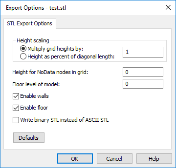
The STL Export Options dialog is displayed when saving a grid in the STL Stereolithography 3D Mesh file format.
|
|
|
Control model scaling and features in the STL Export Options dialog. |
Grid Height Scaling
The grid Z values can be scaled in one of two methods. Select Multiply grid heights by to apply a scale factor to the grid Z values. Select Height as a percent of diagonal length to scale the maximum height of the model as a percentage of the grid's diagonal length.
Scale the grid Z values by selecting Multiply grid heights by and typing a scaling factor in the field. Values less than 1 decrease the grid Z values. Values greater than 1 increase the grid Z values. The default value is 1, where grid Z values are not scaled when saving the grid in the STL format.
Scale the grid Z values by selecting Height as a percent of diagonal length and typing a percentage in the field. Values less than 100 make the model height less than the model's diagonal length. Values greater than 100 make the model height greater than the model's diagonal length. A value of 100 makes the model height equal to the model's diagonal length.
The Height for NoData nodes in grid value is scaled by the Height scaling . The Floor level of model value is not affected by the Height scaling.
NoData Node Value
Specify the value for NoData grid nodes in the Height for NoData nodes in grid field. Nodes assigned the NoData value will be mapped to the Height for NoData nodes in grid value in the output STL file. The default value is 0. However, 0 may not be appropriate for your grid range. A value equal to or near the grid Z minimum is recommended.
The Height for NoData nodes in grid value is transformed by the specified Height scaling . For example, if you remap NoData grid nodes to 100 and set Multiply grid heights by to 0.25, the resulting height value in the STL file is 25 for NoData nodes.
Floor Level
Specify the floor level for the STL model in the Floor level of model field. The Floor level of model value determines the surface's height above the floor and the wall height. The default value is 0. However, 0 may not be appropriate for your grid range.
The Floor level of model value is not affected by the Height scaling.
Walls and Floors
Check the Enable walls check box to include walls in the output STL file. Check the Enable floor check box to include a floor on the bottom of the output STL file. The Enable walls and Enable floor check boxes are checked by default.
File Format
Check the Write binary STL instead of ASCII STL check box to write the STL in the binary format standard. Binary format output STL files are considerably smaller than ASCII format STL files. Clear the Write binary STL instead of ASCII STL check box to write the STL in the ASCII format standard. See the file description for more information on the binary and ASCII formats.
Defaults
Click the Defaults button to reset the export options to their default values.
OK and Cancel
Click OK to save the grid as a model in the STL file format. Click Cancel to close the STL Export Options dialog without saving the STL file.