Grid Mosaic
The Grids | Resize | Mosaic command combines two or more input grids of the same coordinate system into a single output grid. For example, if you have four USGS SDTS Raster Profiles (.DEMs), you can easily combine them into one grid with Grids | Resize | Mosaic.
Grid Mosaic Dialog
Click the Grids | Resize | Mosaic command or the  button, specify the grid file to mosaic in the Open Grid(s) dialog, and click Open to display the Grid Mosaic dialog.
|
|
|
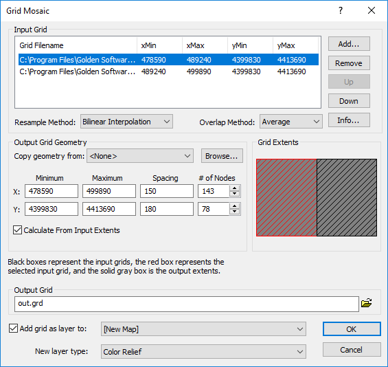
Use the Grid Mosaic dialog to combine two or more input grids into a single output grid. |
Input Grid
The Input Grid group initially contains all the grid files selected in the Open Grid(s) dialog. You can Add or Remove grids to the Input Grid group. When a grid is selected in the Input Grid group, the grid is highlighted in the Grid Extents section.
Header Button Size and Sorting
The Input Grid header buttons can be dragged side to side to make the columns wider or narrower. Also, the grids can be sorted by clicking on the Grid Filename, xMin, xMax, yMin, and yMax headers. Double-clicking the header buttons reverses the direction.
Add
Click the Add button to open the Open Grid(s) dialog and add additional grids to the mosaic. Added grids will be listed in the Input Grid Files section. All grids must be in the same coordinate system. For example, this means that 30 meter DEM files must be in the same UTM zone.
Remove
Select a grid and click the Remove button to remove a grid from the mosaic. One grid can be removed at a time.
Up and Down Buttons
Alternatively, the grids can be moved around the list by highlighting a grid name (click on it) and then clicking the Up and Down buttons.
Info
Click the Info button to obtain information about the selected grid, including the grid file name and statistics. If the grid file is large, click OK in the message box that appears to create a detailed grid report or click Cancel to create a shorter, less detailed grid report.
Resample Methods
There are three Resample Methods from which to choose: Bilinear Interpolation, Nearest Neighbor, and Cubic Convolution.
Overlap Method
When grids overlap, choose an Overlap Method to determine the value of the grid node in the new grid: Average, First, Last, Minimum, Maximum, or Sum. The First and Last are the first and last grids listed in the Input Grid Files section.
Output Grid Geometry
Output Grid Geometry defines the grid limits and grid density. Grid limits are the minimum and maximum X and Y coordinates of all grid files. The default grid Spacing is set to the minimum spacing of the input grids. The # of Nodes in the X direction is the number of grid columns, and the # of Nodes in the Y direction is the number of grid rows. Increasing the grid extents will not increase the grid as the resampling methods do not extrapolate beyond the extents of the original grid.
Copy Geometry
The Copy geometry from option copies the grid geometry from an existing map layer or grid file. This option is useful when creating grids that will become overlaid map layers, processed with the Grid Math command, or used to calculate a volume between two surfaces. The Math and Volume commands require the input grids to have the same geometry.
To copy the geometry from an existing layer, select the layer in the Copy geometry from list. To copy the geometry from a grid file, click Browse and select the file in the Open Grid dialog. Select <None> to return the Output Grid Geometry options to their default values and to manually edit the grid geometry.
Calculate From Input Extents
Check the Calculate From Input Extents box to return the grid to its original size based on the input grids' minimum and maximum.
Grid Extents
The Grid Extents group graphically displays the Input Grid files. Each grid that is added to the Input Grid files group is displayed in the Grid Extents group. Black boxes represent input grids. Red boxes represent the selected input grid. The solid gray box represents the output extents. The input grid boxes can be clicked with the mouse to graphically select the grid in the Grid Extents group. Alternatively, select a grid file in the Input Grid files group to select a grid box.
Output Grid
Choose a path and file name for the grid in the Output Grid section. You can type a path and file name, or click the ![]() button to browse to a new path and enter a file name in the Save Grid As dialog.
button to browse to a new path and enter a file name in the Save Grid As dialog.
Add New Map or Layer
Check the Add grid as layer to check box to automatically add the created grid to a new or existing map. Select [New Map] in the Add grid as layer to field to create a new map. Click the current selection and select an existing map to add a new layer to the map. Select the layer type by clicking the current selection in the New layer type field and selecting the desired layer type from the list.
Note: If you are saving the grid file in the DEM grid format, clear the Add grid as layer check box and add the map or layer with a Home | New Map or Home | Add to Map | Layer command.
To Combine (Mosaic) Grids
- Click the Grids | Resize | Mosaic command or the button.
- Select the files you would like to combine in the Open Grid(s) dialog. If the grid files are in the same folder, use the CTRL and SHIFT keys while clicking on the file names to make multiple selections. If the files are not in the same folder, you will have the opportunity to select more files later. Click Open
- In the Grid Mosaic dialog, choose the desired Resample method and Overlap method. You can also set the Output Grid Geometry .
- Name the new grid in the Output Grid box by typing a path and file name or using the
 button to browse to a new path.
 - Click OK and the new grid is created.
Mosaic Tips
- When a NoData node overlaps a node with a value, the NoData node is ignored.
- The default output grid spacing is set to the minimum spacing of the input grids.
- By specifying First for the Overlap Method, a second overlapping grid can be used to fill in NoData values in the first grid.
- Some grid files, such as USGS DEM files, are not seamless. Occasionally, a grid node is missing along an edge. Sometimes, the reported corner points for adjacent files are slightly different, which causes the neat lines between grids to be slightly off, which causes some edge nodes to be excluded from both grids. This shows up as a NoData node along the seam.
- It is possible to resample a single grid with Grids | Resize | Mosaic by specifying a single grid and changing the grid spacing.
Grid Mosaic and .GSR2 Files
When the input .GRD file for a Grids | Resize | Mosaic command has a defined .GSR2 file with coordinate system information, the information from the first input .GRD file is used for the output .GRD file. All .GRD files should be in the same coordinate system. The Export Options dialog appears with the option to save the coordinate system information. It is recommended to check the GS Reference (Version 2) file if you intend to use the grid file in Surfer, as the GSR2 retains all of the information needed. The grid has the same coordinate system as the original file, but the .GSR2 is required to define the coordinate system.