Import Image - 3D View
The 3D View | Tools | Import Image ( )command imports an image and displays it as a slice in the 3D View window.
|
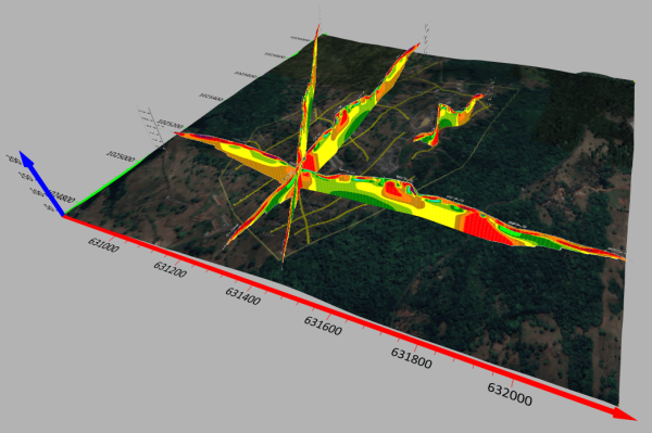
| This image shows a 3D View with three images oriented over a surface topography grid. |
Properties
Properties for an image in the 3D View are described below.
|
|
|
|
|
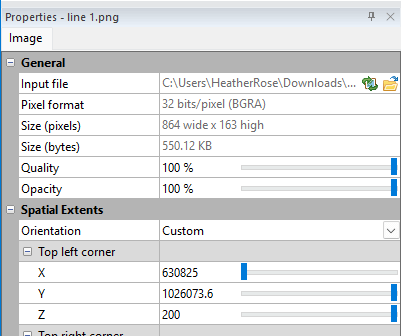
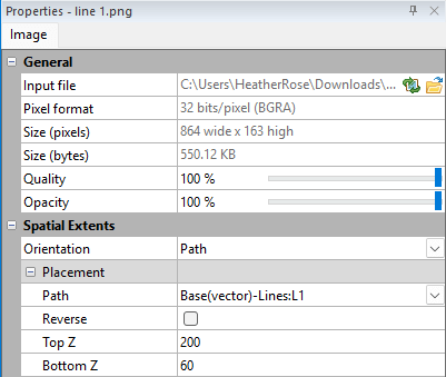
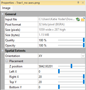
Properties available for an Image in the 3D View. |
||
General
Input File
The Input File lists the file path and file name of the imported image file
-
Reload : Click the
 button to load an updated version of the image from the Input file location
 -
Open : Click the
 button to display the Import dialog. This allows you to select a new image or an updated version of the current image to display. If the file exceeds the current model limits, you will be prompted to adjust the limits.
Pixel Format
All images are converted to 32 bits/pixel BGRA format for use in the 3D View.
Size (pixels)
Displays the pixel dimensions of the input image file
Size (bytes)
Displays the image file size in bytes.
Quality
Adjusts the quality of the image display. As the quality is decreased from 100, the number of pixels used to display the image is decreased. A quality value of 1 will result in a mostly unrecognizable image.
A lower quality may improve rendering speeds for large high resolution images.
Opacity
Change the Opacity of an image by entering a value from 0% (completely transparent) to 100% (completely opaque) or dragging the slider to change the opacity percentage.
Spatial Extents
The spatial extents are used to position the image in the 3D model. Images can be placed along a polyline or polygon, aligned with the plane of two axes, or positioned on a custom plane.
Default import settings/locations
-
GeoTIFF images are imported in the XY plane at the central Z position. By default, the X and Y coordinates of the georeferenced image are used to position the image on the XY plane.
-
All other images are imported to the YZ plane at the central X position by default.
Use Georeferencing
The Use georeferencing box is checked by default when a GeoTIFF is imported. Uncheck this box to manually adjust the XY coordinates of the image
Z position
Move the image up or down in the model by adjusting the Z position.
Type a new value or click and drag the  to the desired Z value.
Orientation
Choose the direction and method for positioning the image within the 3D model. You can set the image to lie on one of the three standard orthogonal planes: XY plane (axial), XZ plane (coronal), or YZ plane (sagittal). Additionally, you can select advanced options to position the image along a polyline, a polygon, or a custom plane. To change the Orientation, click on the existing option and select the desired option.
XY
Images oriented on the XY plane have the following coordinate options. To adjust the orientation using these options, enter a value or click and drag the slider. The slider values are based on the corresponding axis extents.
-
The Z position determines where along the Z axis the image is placed.
-
Left X controls the placement of the left side of the image.
-
Right X controls the placement of the right side of the image.
-
Top Y controls the placement of the top of the image.
-
Bottom Y controls the placement of the bottom of the image.
XZ
Images oriented on the XZ plane have the following coordinate options. To adjust the orientation using these options, enter a value or click and drag the slider. The slider values are based on the corresponding axis extents.
-
The Y position determines where along the Y axis the image is placed.
-
Left X controls the placement of the left side of the image.
-
Right X controls the placement of the right side of the image.
-
Top Z controls the placement of the top of the image.
-
Bottom Z controls the placement of the bottom of the image.
YZ (default)
Images oriented on the XY plane have the following coordinate options. To adjust the orientation using these options, enter a value or click and drag the slider. The slider values are based on the corresponding axis extents.
-
The X position determines where along the X axis the image is placed.
-
Left Y controls the placement of the left side of the image.
-
Right Y controls the placement of the right side of the image.
-
Top Z controls the placement of the top of the image.
-
Bottom Z controls the placement of the bottom of the image.
Custom
Images with a custom orientation allow you to define the X, Y, and Z coordinates for the Top left corner, Top right corner, Bottom left corner, and Bottom right corner. To adjust the orientation using these options, enter a value or click and drag the slider. The slider values are based on the corresponding axis extents but any value can be entered.
Path
Images with a Path orientation are warped to follow the selected polyline or polygon object. This option allows you to position the image along complex, non-planar paths, which can be straight or curved. To adjust the orientation using these options, enter a value or click and drag the slider. The slider values are based on the corresponding axis extents.
-
Path : Select a polyline or polygon object from a base layer in your map. The available objects are listed in the format layername:objectname.
-
Reverse : If the image is imported backwards along the path, check this box to reverse its direction.
-
Top Z and Bottom Z : These controls define the height range and location of the image along the Z axis.
-
If the polyline or polygon is a 3D object, the default Z placement will position the image just above the polyline.
-
If the polyline or polygon is a 2D object, the default Z range will span the minimum and maximum Z extents of the entire 3D model.
-
Helpful Notes for Path Placement
When using Path orientation, keep the following suggestions in mind to ensure your image is placed and displayed correctly:
-
Naming: To quickly identify the correct source object, name your polyline or polygon in the 2D view before setting the path orientation in the 3D View.
-
Transparency: Use file formats such as PNG or TIF to preserve transparent backgrounds in profile images, preventing unwanted white borders.
-
Alignment: If your image includes axes or labels, you may need to extend the polyline/polygon's length to ensure the full image profile is correctly displayed and aligned along the path.