Create/Edit Fly-Through
Click the 3D View | Fly-Through | Create/Edit command or the  button to create or edit a fly-through. A fly-through moves the camera along a path specified by the vertices of a vector object. The Flight Path Editor is displayed when the 3D View | Fly-Through | Create/Edit command is clicked.
Fly-throughs can be played from the 3D view or recorded and saved as an AVI file once a fly-through has been created.
A flight path is defined by key frames. A key frame is a rendering of the 3D view at a specific time with a specific camera position and aim. The camera position and aim are interpolated between the key frames to generate the remaining frames for the fly-through animation. The key frame positions are listed in the Key Frame list in the Flight Path Editor.
Freehand recording
While the Fly-Through feature records a video along a predefined path, you can use the Record Video feature to capture a video of the plot window with freehand camera control. This allows you to manually control the camera's movement and perspective as you record.
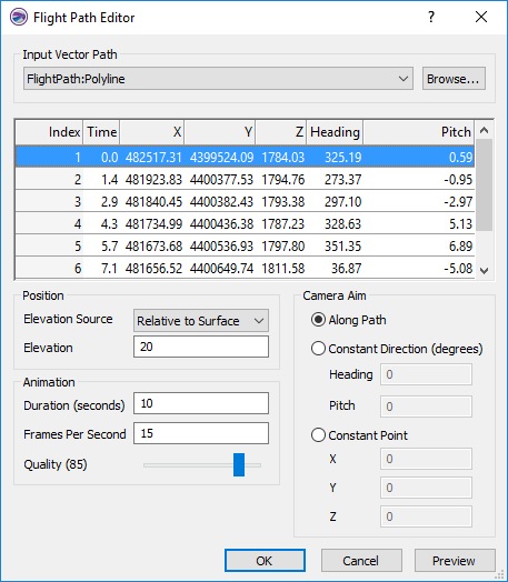
Flight Path Editor
The Flight Path Editor defines the path, camera aim, duration, and quality for the flight path.
|
|
|
Create or edit the flight path in the Flight Path Editor. |
Input Vector Path
Define the vector feature for the flight path in the Input Vector Path section. Select a vector feature from a layer in the map from the Input Vector Path list. The features are listed by layer name and feature name, separated by a colon. For example, in the image above FlightPath is the base (vector) layer name and Polyline is the feature name. The Key Frame list is updated after a vector feature is selected.
Click Browse to load a vector flight path from a file. If the file includes more than one feature, only the first feature will be used to define the Input Vector Path.
If a 3D polyline or 3D polygon is selected as the flight path, only the XY coordinates will be used. The camera elevation will still be determined by the Position settings.
Key Frame List
The Key Frame list displays the Index, Time, camera position, and camera aim for the key frames in the flight path.
- The Index value shows the order of the key frames.
- The key frame Time is determined by the Duration and the distance between key frames.
- The key frame camera X and Y positions are specified by the Input Vector Path feature's vertices.
- The camera's Z position is defined by the properties in the Position group.
- The key frame camera Heading and Pitch are defined by the properties in the Camera Aim group.
Position
The Position group controls the Z position of the camera for the key frames. The Elevation Source determines whether the Z position is relative to the surface or an absolute elevation. For 3D grids, the surface is the central Z plane.
Select Relative to Surface to specify an elevation for the key frame Z positions above or below the surface in the Elevation field. Negative values position the camera below the surface, and positive values position the camera above the surface. The Key Frame list is updated when a value is typed in the Elevation field.
Select Absolute Height to set a single Z position for all key frames in the Elevation field. Type the Z position for the key frames in the Elevation field.
Camera Aim
The Camera Aim group controls the camera aim for the key frames. Three Camera Aim options are available: Along Path, Constant Direction, Constant Point. The Camera Aim options control the Heading and Pitch for the key frames.
Heading is the direction the camera is pointing, and it is greater than or equal to 0 and less than 360 degrees. A heading of 0 degrees is pointing parallel to the increasing y-axis direction, i.e. North. Heading increases as the direction rotates clockwise. A heading of 90 degrees is parallel to the increasing x-axis direction, i.e. East.
Pitch is the rotation of the camera about its lateral axis. In other words, it is a measure of how much the camera is pointing up or down. The Pitch value must be greater than -90 degrees and less than 90 degrees. A Pitch of 0 degrees is looking directly ahead. A positive pitch value has the camera pointed up, and a negative pitch value has the camera pointed down.
Along Path
Select Along Path to orient the camera along the flight path at each key frame.
Constant Direction
Select Constant Direction (degrees) to set a single Heading and Pitch for all key frames.
Constant Point
Select Constant Point to specify a target X, Y, and Z position for the camera aim. The key frame Heading and Pitch values will be updated where the camera is aimed at the target position at each key frame. Type the desired target coordinates in the X, Y, and Z fields.
Animation
The Animation group controls the fly-through Duration, Frames per second, and Quality.
Duration
The Duration (seconds) option defines the length of the fly-through in seconds. The camera moves at a constant velocity along the flight path. The Duration (seconds) value and flight path distance defines the time between each key frame. The flight Duration (seconds) value must be greater than or equal to 1.
Frames per Second
The Frames per second option specifies the number of frames generated per second in the fly-through. A large Frames per second value generates a smoother fly-through, but it also requires more processing time and generates a larger AVI file. With small Frames per second values, the fly-through will appear choppy, but it will also process faster and generate a smaller file. The Frames per second value must be greater than or equal to 2.
Preview and Save Changes
Click Preview to view a preview of the fly-through with the current Flight Path Editor settings. Once the preview is complete, the Flight Path Editor is displayed again. Click OK to save the changes to the fly-through. Click Cancel to close the Flight Path Editor without saving any changes.
The Play and Record commands are enabled after the fly-through is created.