Import Points Dialog
The Import Points dialog specifies the input LAS/LAZ files, the source file elevation units, the layer source coordinate system, and various data filters for the input data. The Import Points dialog is displayed when creating a point cloud layer or when changing the Sources for the layer in the General page.
The Import Points dialog is also displayed when opening an SRF file and one or more LAS source data files were not found. Missing files are highlighted in red and include the error message, "Unable to open file <filename>." Click Update File Path to update the path to the missing data files, or click  to remove the missing files from the Files list.
|
|
|
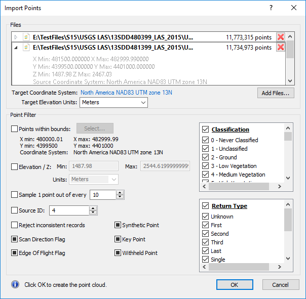
Select the source data and point filtering for the point cloud layer in the Import Points dialog. |
Files
The Files section lists the source data files. The Files section includes commands for adding and removing source files, specifying the data elevation units, and setting the output layer coordinate system.
File List
The File list displays the source LAS/LAZ files, the number of points in the file, the file XYZ extents, and the file coordinate system. Click the  to expand the file details in the file list. Click the
  to collapse the file details in the file list. When a source file is collapsed, only the file name and number of points are displayed.
Source files with errors will be highlighted in red. The error description is displayed below the file name when there is a source file error. Errors must be resolved before the OK button is enabled and the point cloud layer can be created.
File Extents
The spatial extents of the source data is displayed below the file name. The extents include the X Min, X Max, Y Min, Y Max, Z Min, and Z Max.
Source Coordinate System
The Source Coordinate System is displayed below the file spatial extents. The source data files can have different coordinate systems. All coordinates will be converted to the Target Coordinate System.
The Source Coordinate System will be set automatically if the coordinate system information is available in the data file. If the Source Coordinate System is incorrect, click Set to specify the source data coordinate system.
When the Source Coordinate System is unknown for one or more files, the Set all unreferenced option is available. Click Set all unreferenced to specify the same coordinate system for all source files that are currently unreferenced.
Source Elevation Units
The Source Elevation Units are displayed below the Source Coordinate System. The source data files can have different elevation units. All elevation units will be converted to the Target Elevation Units.
The Source Elevation Units may be determined automatically if the information is available in the source file. Click Set to change the elevation units to the appropriate units if the Source Elevation Units is incorrect.
When one or more source file Elevation Units are Unknown, the Set all unknown option is available. Click Set all unknown to specify the same Elevation Units for all source files that currently have their Elevation Units set to Unknown.
Remove Files
Click the to the right of the points count to remove a file from the File list.
Add Files
Click Add files to add new files to the File List with the Open dialog. More than one file from the same directory can be selected. Only LiDAR data files can be selected for creating a point cloud layer.
Target Coordinate System
The Target Coordinate System is the coordinate system to which all the source file coordinates are transformed. This becomes the point cloud layer source coordinate system when the point cloud layer is created.
Target Elevation Units
Select the Target Elevation Units from the Target Elevation Units list. The source elevation values will be converted to the corresponding value in the Target Elevation Units in the point cloud layer.
Point Filter
The points in the input files can be filtered by various criteria in the Point Filter section.
Boundary Filter
The Points within bounds filter limits the imported points by XY extents. Select the Points within bounds check box to apply the Points within bounds filter. Click Select to set the bounds in the Select Bounds dialog. The minimum and maximum XY values and their coordinate system are displayed below Points within bounds.
Elevation/Z Filter
The Elevation / Z filter limits the imported points to a specific elevation/Z value range. Select the Elevation / Z check box to apply the Elevation / Z filter. Specify the minimum Z value to be imported in the Min field. Specify the maximum Z value to be imported in the Max field.
Select the units for the Min and Max values from the Units list. The Source Elevation Units must be specified in the Files list to use the Elevation / Z Units . If any input file has Source Elevation Units set to Unknown , then the Elevation / Z Units must also be set to Unknown . When set to Unknown , the Z values are compared directly to the Min and Max values without any unit conversions.
Sample Filter
The Sample 1 point out of every filter limits the imported points to every nth point. Select the Sample 1 point out of every check box to apply the sample filter. For example to import every other point, type 2 in the Sample 1 point out of every field. Type 10 to import every tenth point. Click the  buttons to increase or decrease the value, or type a value directly in the Sample 1 point out of every field.
Source ID Filter
The point source ID value indicates the file from which the point originated. The point source ID is a value from 0 to 16384 inclusive. Select the Source ID check box to apply a source ID filter to the data. Type the desired source ID number in the Source ID field to limit the import to points with the specified point source ID.
Reject Inconsistent Records
The Reject inconsistent records filter removes all invalid or inconsistent data from import. Select the Reject inconsistent records check box to reject invalid or inconsistent data.
Scan Direction Flag
The scan direction flag indicates whether the point was located on a forward scan sweep or backward scan sweep. The Scan Direction Flag filter limits the imported points to forward scan sweep data, backwards scan sweep data, or both. Click the Scan Direction Flag check box to change the filter state.
A check mark  indicates only forward scan sweep points are imported. A cleared check box
 ![]() indicates only backwards scan sweep points are imported. A black square
indicates only backwards scan sweep points are imported. A black square  indicates no scan direction filtering is applied. No Scan Direction Flag filter is applied by default.
Edge of Flight Flag
The edge of flight flag indicates whether the point is located at the farthest reach of the scanner during the sweep. The Edge of Flight Flag filter limits the imported points to points with the edge of flight flag, points without the edge of flight flag, or both. Click the Edge of Flight Flag check box to change the filter state.
A check mark indicates only points with an edge of flight flag are imported. A cleared check box ![]() indicates only points without an edge of flight flag are imported. A black square indicates no edge of flight filtering is applied. No Edge of Flight Flag filter is applied by default.
indicates only points without an edge of flight flag are imported. A black square indicates no edge of flight filtering is applied. No Edge of Flight Flag filter is applied by default.
Synthetic Point
The synthetic point flag indicates the point was created by a means other than LiDAR collection, such as a point created via interpolation in post-processing software or digitized from a photogrammetric stereo model. The Synthetic Point filter limits the imported points to points with the synthetic point flag, points without the synthetic point flag, or both. Click the Synthetic Point check box to change the filter state.
A check mark indicates only points with a synthetic point flag are imported. A cleared check box ![]() indicates only points without a synthetic point flag are imported. A black square indicates no synthetic point filtering is applied. No Synthetic Point filter is applied by default.
indicates only points without a synthetic point flag are imported. A black square indicates no synthetic point filtering is applied. No Synthetic Point filter is applied by default.
Key Point
The key point flag indicates the point is considered a model key point and should not be removed. The Key Point filter limits the imported points to points with the key point flag, points without the key point flag, or both. Click the Key Point check box to change the filter state.
A check mark indicates only points with a key point flag are imported. A cleared check box ![]() indicates only points without a key point flag are imported. A black square indicates no key point filtering is applied. No Key Point filter is applied by default.
indicates only points without a key point flag are imported. A black square indicates no key point filtering is applied. No Key Point filter is applied by default.
Withheld Point
The withheld point flag indicates the point is considered suspect or redundant and should not be included in processing. The Withheld Point filter limits the imported points to points with the withheld point flag, points without the withheld point flag, or both. Click the Withheld Point check box to change the filter state.
A check mark indicates only points with a withheld point flag are imported. A cleared check box ![]() indicates only points without a withheld point flag are imported. A black square indicates no withheld point filtering is applied. No Withheld Point filter is applied by default.
indicates only points without a withheld point flag are imported. A black square indicates no withheld point filtering is applied. No Withheld Point filter is applied by default.
Classification Filter
The Classification filter limits the imported points to only the selected classes. Select the Classification check box to import all classes. Clear the Classification check box to clear all the classes. Select individual classes for import by selecting the check boxes next to the desired classes.
Return Type Filter
The Return type filter limits the imported points to only the specified return types. The return types are defined by the return number and number of returns from the pulse. For example, Single selects all points with a return number of 1 and a number of returns of 1. The following table defines the Return type options.
|
Option |
Definition |
|
Unknown |
The return number is unknown |
|
First |
Return Number = 1 |
|
Second |
Return Number = 2 |
|
Third |
Return Number = 3 |
|
Last |
Return Number = Number of Returns |
|
Single |
Return Number = Number of Returns = 1 (e.g. 1st of 1) |
|
First of Many |
Return Number < Number of Returns AND Return Number = 1 (e.g. 1st of 3) |
|
Second of Many |
Return Number < Number of Returns AND Return Number = 2 (e.g. 2nd of 4) |
|
Third of Many |
Return Number < Number of Returns AND Return Number = 3 (e.g. 3rd of 4) |
|
Last of Many |
Return Number = Number of Returns AND Return Number > 1 (e.g. 2nd of 2, 3rd of 3, etc.) |
Select the Return type check box to import all return types. Clear the Return type check box to clear all the return types. Select individual return types for import by selecting the check boxes next to the desired return type.