Block Render
The 3D View | Tools | Add to 3D Grid | Block Render command creates a block render from a 3D grid in the 3D View window.
A block render displays the blocks of an input lattice. How these blocks are sized and colored depends on the selected Placement method. If a required grid node has a null or NoData value, that block is not displayed. Additionally, the block is not displayed if the colormap value for the block's component value is 0% opaque.
Creating a Block Render
A block render can be created using the 3D View | Tools | Add to 3D Grid | Block Render command from the 3D View window. This command will only be available when a 3D grid is selected in the Contents window. Additional block renders can be created by clicking the command again.
General Properties
Properties for block renders are described below.
|
|
|
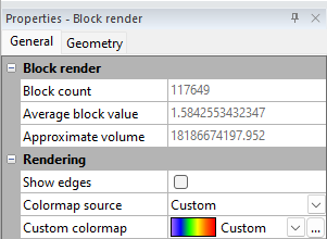
This image shows the General Properties available for adjustment with Block renders. |
Block Render
The block render section displays information about the model that updates dynamically as the properties are adjusted and blocks are made transparent by the colormap or geometry. Only fully transparent blocks (0% opacity) are excluded from these calculations.
-
Block count displays the number of non-transparent blocks that are visible in the model.
-
Average block value displays the average C value of all visible blocks.
-
Approximate volume displays the total volume for all of the visible blocks in the model
Show Edges
Check the box next to Show edges to display lines around the face for each block. When this option is unchecked, lines are not displayed.
Edge Color
The Edge color defines the color of the lines that are around each block face. To change the color, click on the existing color and select a new color from the list or, click the Custom colormap button to open the Colors dialog, where custom colors can be defined.
Colormap Source
The Colormap Source field controls the colormap used to color the block render. By default, the block render will use the existing colormap assigned to the Volume Render. To assign a colormap to the block render independently, the Custom option can be used.
Note that the opacity map for a block render will always default to 100% regardless of the Volume Render colormap settings.
Custom Colormap
When the Colormap Source is set to Custom, the Custom Colormap field becomes available. This field is used to define a colormap for the block render independently of the colormap used for the volume render or the slice in the 2D Plot.
Geometry
The extents of a block render module are controlled with the geometry properties.
|
|
|
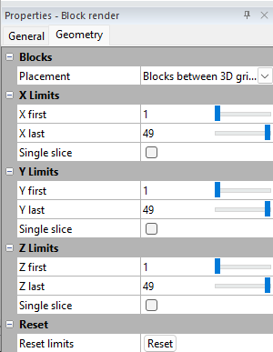
This image shows the Geometry Properties available for adjustment with Block renders. |
Placement
The Placement setting controls how the blocks are generated relative to the input grid nodes:
-
Blocks between 3D grid nodes (default): Each block has corners at the surrounding eight grid nodes. The block's value and color are determined by interpolating (averaging) the eight corner grid node component values. All blocks have a consistent size.
-
Blocks centered at 3D grid nodes: Each block is centered at a single grid node. The block's value and color are not interpolated; they represent the exact value of that single node. Blocks on the edges of the model are smaller because they do not extend beyond the grid extents.
X Limits
The X Limits section displays the limits in the X direction for the Block render. The X first value is the first grid node to be displayed. The X last value is the last grid node to be displayed. Values for X first and X last are index values for the X direction. The first node in the direction in the input grid is 1. The next node is 2, and so on. To change the value, highlight the existing value and type the desired value or click and drag the slider to increase or decrease the index grid node value.
Check the Single slice check box to view a single block thick slice of the Block render in the X direction. When the Single slice check box is checked, the X first value determines which grid node is visible. The X last property is disabled. Type the desired value into the X first field to view a specific slice. Click and drag the slider to pan through the 3D grid.
Y Limits
The Y Limits section displays the limits in the Y direction for the Block render. The Y first value is the first grid node to be displayed. The Y last value is the last grid node to be displayed. Values for Y first and Y last are index values for the Y direction. The first node in the direction in the input grid is 1. The next node is 2, and so on. To change the value, highlight the existing value and type the desired value or click and drag the slider to increase or decrease the index grid node value.
Check the Single slice check box to view a single block thick slice of the Block render in the Y direction. When the Single slice check box is checked, the Y first value determines which grid node is visible. The Y last property is disabled. Type the desired value into the Y first field to view a specific slice. Click and drag the slider to pan through the 3D grid.
Z Limits
The Z Limits section displays the limits in the Z direction for the Block render. The Z first value is the first grid node to be displayed. The Z last value is the last grid node to be displayed. Values for Z first and Z last are index values for the Z direction. The first node in the direction in the input grid is 1. The next node is 2, and so on. To change the value, highlight the existing value and type the desired value or click and drag the slider to increase or decrease the index grid node value.
Check the Single slice check box to view a single block thick slice of the Block render in the Z direction. When the Single slice check box is checked, the Z first value determines which grid node is visible. The Z last property is disabled. Type the desired value into the Z first field to view a specific slice. Click and drag the slider to pan through the 3D grid.
Reset
Click the Reset button to return all of the values to the smallest and largest possible values. Clicking the Reset button does not uncheck any Single slice checkboxes.
Notes on Block Renders
-
Including both a Volume Render and Block Render in the 3D model can result in odd visual effects. It is recommended that one or the other be turned off.
-
All partially transparent blocks are counted toward the volume even if the opacity is 0.01%
-
3D PDF and VRML viewers may not display transparency in the same way that Surfer does.
-
Performance may be impacted when the 3D grid has a high resolution (100x100x100 or higher) even when all CPU cores are available.