3D Polymesh
A 3D polymesh is a collection of vertices, edges and faces that defines the shape of a polygonal object. The faces consist of triangles (triangle mesh), quadrilaterals (quad mesh), or other simple convex polygons (n-gons). The faces are rendered as a polymesh and saved as a .DXF file type. Import the DXF file into Surfer and a base(vector) layer is created in the plot window with the 3D polymesh as a component. Click on the Map object and then click the Map Tools | View | 3D View command to view the polymesh in the 3D view window.
|
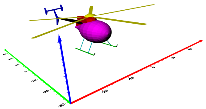
| The AutoCAD drawing of this helicopter is displayed in the 3D View window. |
To Import and View a 3D Polymesh:
- Use the File | Open command.
- Select a DXF file in the Open dialog and click Open.
- Specify options in the DXF Import Options dialog and click OK. The map is automatically created with reasonable defaults.
- Click on the Map object in the Contents window.
- Click the Map Tools | View | 3D View command.
3D Polymesh Tips
- Polymeshes must be imported into Surfer.
- To change the features of the polymesh, click once on the base(vector) layer in the plot window or on the polymesh in the Contents window to select it.
- Single-color meshes will be rendered as solid-color faces but if each face has a different color then the faces will render as separate colors.
- Meshes with colors per vertex render as colored wireframe polymeshes.
- Textured meshes render as black wireframes.
- Click on the Map object in the Contents window. On the View page in the Properties window, check that the Tilt is 90°. Angles other than 90° may distort the polymesh in the 3D view window.
Polymesh Layer Properties
A polymesh cannot be edited in Surfer. Only the Info page is included in the polymesh properties.