Drawing Contours
When you create a contour map, the grid file is read into the plot window as an internal array of X, Y, and Z grid nodes. The grid nodes consist of rows and columns of Z values. The rows contain grid nodes with the same Y coordinate, and the columns contain grid nodes with the same X coordinate. Grid file columns and rows are sometimes referred to as X grid lines and Y grid lines, respectively. The intersection of a row and column is defined as a grid node. Grid files define the X, Y location of each grid node over the extent of the map, and the interpolated Z value at each node.
|
|
|
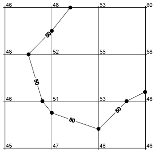
The path of a contour line (Z = 50) through a grid is defined by interpolating between grid nodes. This example shows the straight-line segments that define the contour line. The dots are added to show the ends of each line segment. |
When Surfer creates a contour map, the contour lines are drawn as a series of straight line segments between adjacent grid lines. The point where a contour line intersects a grid line is determined by interpolation between Z values at adjacent grid nodes.
The grid limits define the extent of contour maps. Once a grid file is created you cannot produce a contour map larger than the extent of the grid file. However, you can use the Limits page to specify a subset of the grid used to create the contour map.
