Grid Spline Smooth
The Grids | Edit | Spline Smooth command uses cubic spline interpolation to compute new grid nodes. The interpolation simulates a drafting technique where a flexible strip (a spline) is used to draw a smooth curve between data points. Spline smoothing does not extrapolate beyond the edge of the original grid file. The original grid limits are used to define the grid limits for the smoothed grid. Spline smoothing does not retain faulting information.
A spline is really nothing more than the graphs of a set of contiguous (end-point adjacent) cubic polynomials with the same slopes at their endpoints. Cubic spline smoothing may increase the maximum Z value and decrease the minimum Z value from the input grid.
There are two ways to perform spline smoothing; by expanding the grid or by recalculating the grid.
Expanding a Grid
When a grid is expanded, the original grid nodes are preserved in the smoothed grid, and new grid nodes are added between existing grid nodes. The number of added grid nodes is defined in the Spline Smooth dialog by the Number Nodes to Insert boxes.
Original Grid:
|
o |
o |
o |
o |
o |
|
o |
o |
o |
o |
o |
|
o |
o |
o |
o |
o |
Expanded Grid:
|
o |
x |
x |
o |
x |
x |
o |
x |
x |
o |
x |
x |
o |
|
x |
x |
x |
x |
x |
x |
x |
x |
x |
x |
x |
x |
x |
|
x |
x |
x |
x |
x |
x |
x |
x |
x |
x |
x |
x |
x |
|
o |
x |
x |
o |
x |
x |
o |
x |
x |
o |
x |
x |
o |
|
x |
x |
x |
x |
x |
x |
x |
x |
x |
x |
x |
x |
x |
|
x |
x |
x |
x |
x |
x |
x |
x |
x |
x |
x |
x |
x |
|
o |
x |
x |
o |
x |
x |
o |
x |
x |
o |
x |
x |
o |
A simple three by five grid is shown on the top in the above example. Each grid node is represented by an "o". When expanding the grid, two grid nodes are inserted between each existing grid node to produce the grid on the bottom. The original grid nodes are indicated with "o", and the new grid nodes are indicated with "x." The original grid is three by five and the smoothed grid is seven by thirteen.
To Expand a Grid
- Click the Grids | Edit | Spline Smooth command or the
 button.
 - In the Spline Smooth dialog, specify the input grid from a map layer or grid file in the Input Grid section.
- Click the Insert Nodes option in the Method section.
- In the Number Nodes to Insert section, enter the number of nodes to insert. Or, use the up and down arrows to change the values. As you make the changes, the number of rows and columns to be produced in the smoothed grid is indicated in the Final Grid Size section.
- The Between Rows box specifies the number of rows to insert between the existing rows in the grid file. Rows correspond to grid nodes of constant Y.
- The Between Cols box specifies the number of columns to insert between the existing columns in the grid file. Columns correspond to grid nodes of constant X.
- If you need information on the original grid file, click the
 button in the Input Grid File section to display the number of rows and columns, minimum and maximum X, Y, Z values, and statistics.
 - To change the name for the smoothed grid file, click the
 button in the Output Grid File section, specify the path and file name in the Save Grid As dialog, and click Save.
 - Click OK and the smoothed grid is created.
Recalculating a Grid
When a grid file is recalculated, the number of rows and columns are increased or decreased relative to the original grid. The original grid values are lost unless their locations correspond exactly with the grid nodes in the output grid. The smoothed grid file will still be an accurate representation of the original data. For example, you might have a 75 x 75 grid and need a 100 x 100 grid to perform grid math with another grid. You can recalculate the grid to have exactly the number of rows and columns needed.
To Recalculate a grid:
- Click the Grids | Edit | Spline Smooth command.
- In the Spline Smooth dialog, specify the input grid from a map layer or grid file in the Input Grid section.
- Click the Recalc Grid option in the Method section.
- In the Final Grid Size section, specify the number of rows and columns to produce in the smoothed grid. You can increase or decrease the number of rows and columns in the grid file. Enter the desired value, or use the up and down arrows on your keyboard to change the values for the number of rows and columns to be produced in the smoothed grid.
- The # Rows box specifies the number of rows for the smoothed grid file.
- The # Cols box specifies the number of columns for the smoothed grid file.
- If you need information on the original grid file, click the button in the Input Grid File section to display the number of rows and columns, minimum and maximum X, Y, Z values, and statistics.
- To change the name for the smoothed grid file, click the button in the Output Grid File group, specify the path and file name in the Save Grid As dialog, and click Save.
- Click OK and the smoothed grid is created.
Reduce Grid File Density
Spline smoothing can be used to reduce grid file density. If a dense grid is created, producing a map from this grid might take a considerable amount of time. The less dense grid can be used to produce the contour map or 3D wireframe in less time. USGS GTopo30 files are quite dense and it is necessary to thin them out before attempting to plot a map of the grid.
Fill in a Sparse Grid
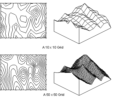
One of the purposes of spline smoothing is to fill in a sparse grid. A map produced from a sparse grid may have an angular appearance. For example, spline smoothing can be used to increase a 10 x 10 grid (a sparse grid) to a 50 x 50 grid. Denser grids produce smoother maps.
|
|
|
Increasing the grid density using spline smoothing increases the roundness or smoothness of the contours and the surface appearance. |
The Spline Smooth Dialog
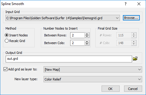
Click the Grids | Edit | Spline Smooth command to open the Spline Smooth dialog.
|
|
|
To expand a grid, choose the Insert Nodes option in the Spline Smooth dialog. When recalculating a grid, choose the Recalc Grid option in the Spline Smooth dialog. |
Input Grid
Specify the source map layer or grid file in the Input Grid section. Click the current selection and select a map layer from the list. Only map layers created from grid files are included in the Input Grid list. Click Browse to load a grid file with the Open Grid dialog.
Insert Nodes
Choose the Insert Nodes option in the Method section to activate the Number Nodes to Insert section.
Number of Nodes to Insert
Choose the Insert Nodes option in the Method section to activate the Number Nodes to Insert section. Enter the number of nodes to insert, or use the up and down arrows to change the values. As you make the changes, the number of rows and columns to be produced in the smoothed grid is indicated in the Final Grid Size section.
Insert Nodes Between Rows
The Between Rows box specifies the number of rows to insert between the existing rows in the grid file. Rows correspond to grid nodes of constant Y.
Insert Nodes Between Columns
The Between Cols box specifies the number of columns to insert between the existing columns in the grid file. Columns correspond to grid nodes of constant X.
Recalculate Grid
Choose the Recalc Grid option in the Method section to activate the Final Grid Size section. This group specifies the number of rows and columns to produce in the smoothed grid. You can increase or decrease the number of rows and columns in the grid file.
Final Grid Size
Choose the Recalc Grid option in the Method section to activate the Final Grid Size section. This group specifies the number of rows and columns to produce in the smoothed grid. You can increase or decrease the number of rows and columns in the grid file. Enter the # Rows and/or # Cols, or use the up and down arrows to change the values.
# Rows
The # Rows box specifies the number of rows for the smoothed grid file. Enter the desired value, or use the up and down arrows to change the values for the number of rows to be produced in the smoothed grid.
# Columns
The # Cols box specifies the number of columns for the smoothed grid file. Enter the desired value, or use the up and down arrows to change the values for the number of columns to be produced in the smoothed grid.
Output Grid
Type a file path and file name, including the file type extension, in the Output Grid field, or click the ![]() button and specify the path and file name for the grid file in the Save Grid As dialog.
button and specify the path and file name for the grid file in the Save Grid As dialog.
Add New Map or Layer
Check the Add grid as layer to check box to automatically add the created grid to a new or existing map. Select [New Map] in the Add grid as layer to field to create a new map. Click the current selection and select an existing map to add a new layer to the map. Select the layer type by clicking the current selection in the New layer type field and selecting the desired layer type from the list.
Note: If you are saving the grid file in the DEM grid format, clear the Add grid as layer check box and add the map or layer with a Home | New Map or Home | Add to Map | Layer command.
Grid Spline Smooth and .GSR2 Files
When the input .GRD file for a Grids | Edit | Spline Smooth command has a defined .GSR2 file with coordinate system information, this information is used for the output .GRD file. The Export Options dialog appears with the option to save the coordinate system information. It is recommended to check the GS Reference (Version 2) file if you intend to use the grid file in Surfer, as the GSR2 retains all of the information needed. The grid has the same coordinate system as the original grid file, but the new .GSR2 is required to define the coordinate system.