Georeference Image
An image is often used for a base map. Georeferencing is necessary to place unreferenced images in the correct relative position in the coordinate system when overlaying multiple map layers. Occasionally you may need to adjust an already georeferenced image. Georeference an image by selecting the base (raster) layer and clicking the Map Tools | Layer Tools | Georeference Image command or the  button. You can also right-click the base layer in the Contents window or plot window and click Georeference Image in the context menu. Finally, you can georeference an image by clicking Georeference Image in the Properties window General page for the base (raster) layer.
Images must be in a base layer to be georeferenced, and the image must be at least 2x2 pixels to be georeferenced. Images are georeferenced with the Georeference Image window. Use the Home | New Map | Base or Home | Add to Map | Layer | Base command to import an image as a base layer. The Georeference Image command cannot be used with images imported with File | Insert | Graphic.
Georeference Image Window
The Georeference Image window is opened by clicking Map Tools | Layer Tools | Georeference Image, right-clicking the base layer or image object in the Contents window and clicking Georeference Image, or clicking Georeference Image in the Properties window General page for the base (raster) layer.
|
|
|
Calibrate the image and set the warping method in the Georeference Image window. |
The Georeference Image window is a separate window from the Surfer application. You can move back and forth between the windows to verify your changes are correct and to test different warping methods. You can also minimize, maximize, restore, move, and resize the Georeference Image window.
When the Georeference Image window is minimized, the title bar is moved to the lower left corner of your screen. You can click the Restore or Maximize button to restore the window. Alternatively, click the Map Tools | Layer Tools | Georeference Image command or Georeference image button in the Properties window to restore the window.
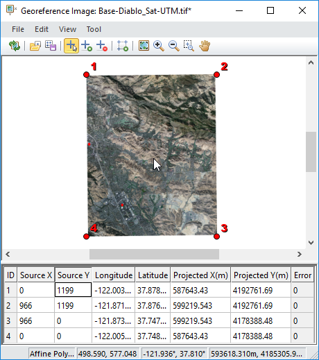
The Georeference Image window displays the image name in the title bar. The Georeference Image window has four menus with various commands and a command toolbar. The window has two panes: a viewer pane that displays the image and control points, and a table that hold georeferencing information about the control points. Click and drag the dividing line between the table and viewer to adjust the relative sizes within the window. The entire window can also be resized by clicking and dragging a side or corner. A status bar is displayed at the bottom of the Georeference Image window.
Menu Commands and Toolbar
The Georeference Image window has four menus: File, Edit, View, and Tool. The File menu commands are used to apply changes to the map and save or load control points. The Edit menu commands edit the control points and sets the warp method. The View menu commands change the view in the view pane. The Tool menu commands change the tool mode for the mouse and cursor.
File Menu Commands
|
Update Map |
Applies the image georeferencing to the map in the Surfer window. |
|
CTRL + U |
|
Load Points |
Loads control points from a Georeference GEOREF file to the control points table. |
|
CTRL + L |
|
Save Points |
Saves the control points to a GEOREF file. |
|
CTRL + S |
|
Close |
Closes the Georeference Image window. |
Edit Menu Commands
|
Undoes the previous action in the Georeference Image window. |
CTRL + Z |
||
|
Redoes the previously undone action. |
CTRL + Y |
||
|
Delete |
Deletes the selected control point or points. |
DEL |
|
|
Select All |
Selects all control points. |
CTRL + A |
|
|
Deselect All |
Deselects all control points. |
||
|
Set Warp Method |
Sets the warp method |
||
|
Add Control Points At Corners |
Adds control points to the four corners of the image. Appends the control points to the end of the control points table. |
|
View Menu Commands
|
Image |
Adjust the view to fit the entire image in the view pane. |
|
|
Changes cursor to zoom in mode. |
|
|
|
Changes cursor to zoom out mode. |
|
|
|
Zoom Selected |
Zooms in to the selected point or points |
|
|
Changes the cursor to pan mode. |
|
|
|
Antialiasing |
Use automatic mode, or turn antialiasing on or off. |


Tool Menu Commands
|
Select Mode |
Changes the cursor to select mode. |
|
|
Add Mode |
Changes the cursor to add point mode. |
|
|
Delete Mode |
Changes the cursor to delete point mode. |
|
View Pane
The view pane displays the source image and control points. The view pane is dynamically linked to the control points table. Selecting, adding, changing, or removing a control point in the view pane automatically selects, adds, changes, or removes the control point in the control point table. Use the View menu commands, toolbar buttons, or mouse wheel to change the view in the view pane.
Antaliasing
By default, the View | Antialiasing | Automatic option is active. When zoomed out, antialiasing is enabled to smooth lines in the image. When you zoom in to the point at which one pixel in the image is 10x10 pixels or larger on the screen, antialiasing is turned off to provide a sharper picture.
However, if you wish to keep antialiasing on or off regardless of zoom level, click the View | Antialiasing | On or View | Antialiasing | Off command.
Control Point Table
The control point table contains information about the source and target coordinates for the control points. At least three control points are required to warp the image. Most warp methods require at least four control points, but there is no limit to the number of control points you can add. At least six columns are displayed in the control point table. Each row represents a single control point. The control point table is dynamically linked to the view pane. Changes made in the control point table are automatically reflected in the view pane. Any missing values or values that result in errors are highlighted in yellow in the control point table.
|
|
|
Enter the control point information in the control point table. |
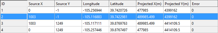
- The ID column contains the ID number for the control point. The ID helps you associate rows with points in the view pane.
- The Source X and Source Y columns contain the pixel location of the control points on the image. The 0,0 point is located at the lower left corner of the image. The maximum values are determined by the number of pixels in the image. The maximum point is located at the upper right corner of the image.
- The Target X and Target Y columns contain the desired coordinates of the control points. The Target X and Target Y columns are displayed when the base layer is assigned an unreferenced local coordinate system. Type the coordinate values for the control point in the Target X and Target Y fields.
- The Longitude and Latitude columns contain the desired coordinates of the control points. The Longitude and Latitude columns are displayed when the base layer is assigned a geographic or projected coordinate system. Type the coordinate values in degrees for the control point in the Longitude and Latitude fields. The values in the Projected X and Projected Y columns are automatically updated when you make a change to the values in the Longitude or Latitude column.
- The Projected X and Projected Y columns contain the desired coordinates of the control points. The Projected X and Projected Y columns are displayed when the base layer is assigned a projected coordinate system. Type the coordinate values in the coordinate system's units for the control point in the Projected X and Projected Y fields. The values in the Longitude and Latitude columns are automatically updated when you make a change to the values in the Projected X or Projected Y column.
- The Errorcolumn displays the RMS error value for each calibration point between the source image and referenced image.
Click a cell to select it. Begin typing to replace the selected cell's contents. Double-click on a cell to enter cell edit mode and edit the current cell contents. When you are finished replacing or editing the cell's contents, press enter, click on another cell, or navigate to another cell with the ARROW keys.
Status Bar
The status bar is displayed at the bottom of the Georeference Image window. The status bar includes three to five sections depending on the base layer's source coordinate system, from left to right:
- A tool tip for the current tool or the command over which the cursor is hovering.
- The selected warp method. No warp method is displayed if Edit | Set Warp Method | Automatic is selected.
- The cursor location in pixel units for all images.
- The cursor location in longitude and latitude units for images with a geographic source coordinate system.
- The cursor location in the coordinate system's units for images with a projected source coordinate system.
You may need to resize the Georeference Image window and/or the status bar sections to see all the status bar sections. Individual sections of the status bar can also be resized by clicking and dragging the separators.
Adding, Removing, Modifying, and Saving the Control Points
Control points are added, removed, and modified with the various commands, actions with the mouse, and/or key strokes. The Georeference Image window must contain at least three control points to warp the image.
Adding a New Control Point
There are three methods for adding control points to the image.
- Click the Tool | Add Mode command or
 button to add points to the image with the mouse. The cursor changes to a crosshair to indicate you are in add mode. Click on the image and a control point is created. Zoom in with the mouse wheel or Zoom In command to precisely place control points.
 - Click the Edit | Add Control Points At Corners command or
 button to add a control point at each corner of the image. Note that aerial photographs may have distortion around the edges, and therefore using control points that are not on the edges may generate a more accurate calibration. However, this depends on if or to what extent there is distortion along the edges and the extents of the image coverage.
 - Click the File | Load Points command or
 button to add control points from a GEOREF file. Loading points from a georeferencing file replaces any existing control points.
Selecting Control Points
Click the Tool | Select Mode command or  button or press ESC to enable select mode. Click a control point to select it. Click and drag in the view pane to block select one or more control points. Click the Edit | Select All command or press CTRL + A to select all control points. Selected points are represented by green symbols and text, while deselected points are represented by red symbols and text. When points are selected in the view pane, the rows with the points are highlighted in the control point table.
Select a control point by clicking anywhere in the control point's row in the table. Select multiple control points by holding CTRL while clicking in different rows. Select a contiguous group of points by clicking the first row you'd like to select, holding SHIFT, and clicking the last row you'd like to select. The two rows you clicked and all rows between are selected.
Moving Control Points
Control points can be moved in the view pane or with the control point table:
- Select one or more control points to move the point or points to a different location on the image. Once you have selected the point you wish to move, click and drag the point to the desired location. All selected points will move the same direction and distance from their original starting location if you have more than one point selected. The Source X and Source Y values in the control point table update automatically for the moved point or points.
- Type a new value in the Source X and/or Source Y column to move a control point. The control point moves in the view pane automatically to reflect the new Source X and Source Y values.
Deleting Control Points
Control points can be deleted by clicking the control point when delete mode is active. Click Tool | Delete Mode or the  button to activate delete mode.
Alternatively, select one more control points with any of the methods listed in the Selecting Control Points section of this topic. Next click the Edit | Delete command or press DEL to remove the control point or points. The point or points are removed from the control point table and view pane.
Saving Calibration Points
Click the File | Save Points command or  button to save the calibration points to a GEOREF file. The GEOREF file can be used with the image source file to quickly georeference the image in other Surfer projects. Alternatively you can export the georeferenced image to a file type that includes georeference information, such as GeoTIFF.
Warp Method
The warp method determines how the image is warped to the control points. Available options are: Affine Polynomial, First Order Polynomial, Second Order Polynomial, Third Order Polynomial, Thin Plate Spline, Natural Cubic Spline, Marcov Spline, Exponential Spline, Rational Quadratic Spline, and Inverse Distance Squared.
Click the Edit | Set Warp Method command and click the desired method from the list to change the warp method. If too few points exist for a warp method, the method is disabled in the Edit | Set Warp Method menu. The number of required control points is displayed before the warp method name. Affine Polynomial requires at least three control points. Second Order Polynomial requires at least six control points. Third Order Polynomial requires at least ten control points. All other methods require at least four control points. Refer to each specific warp method topic for the transformation information and an image demonstrating the warp.
Automatic Warp Method
The Edit | Set Warp Method | Automatic option is checked by default. The default option is determined by the number of control points when the Automatic option is active. When there are three or more control points, the default method is Affine Polynomial.
Turn off automatic warp method selection by clicking the Edit | Set Warp Method | Automatic command to remove the check mark. The status bar will display Unknown and the File | Update Map command will be unavailable if the selected warp method requires more control points.
Applying the Georeferencing to the Map
Click the File | Update Map command or  button to update the map with the image georeferencing. Click on the main Surfer window to view the map and verify the base layer image is satisfactory. When first georeferencing an image, or when making large changes to a georeferenced image, it is likely you will have to adjust the Map object's Limits and Scale to see the image. If the image is not satisfactory, you can change, add, or remove control points or change the warp method. Once the base layer image looks correct, you can close the Georference Image window by clicking the File | Close command or
  button.
If you click the Close command with unapplied changes to the control points, a Surfer dialog is displayed.
|
|
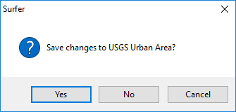
Click Yes to apply your recent changes to the map and close the Georeference Image window. Click No to close the Georeference Image window without applying the changes. Click Cancel to return to the Georeference Image window.
Undoing Changes to the Map
If you wish to revert the changes to the map after clicking the File | Update Map command, the changes must be undone with the plot window Undo command. The action is added to the plot window undo list, because the change happens in the plot window rather than the Georeference Image window. After clicking the Undo command in the plot window, the map will revert back to its previous state. The control points and image in the Georeference Image window will not be changed.