Viewshed Layer General Properties
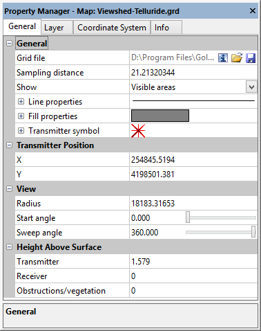
To edit a viewshed layer, click once on the viewshed layer to select it. The properties for the viewshed layer are displayed in the Properties window. The viewshed layer properties General page contains the following options:
|
|
|
Edit the viewshed properties on the General page of the Properties window. |
Input Grid File
The Grid file lists the current grid file used in the viewshed layer. The path and file name are the location of the grid file when the viewshed layer was created or the grid file was most recently changed.
Change File
The  button displays the Open Grid dialog. This allows you to select a new grid file, or an updated version of the grid file used to create the map. Select a grid file and click Open.
If the new grid exceeds the current map limits, another warning will appear asking you to adjust the map limits. If you click Yes, the limits are automatically adjusted to fit the new grid. If you click No, the limits are not automatically adjusted. The map may not be displayed. To change the map limits, click on the Map object in the Contents window and the Limits tab in the Properties window.
You may also see a warning message that the current map scale may result in an un-viewable map. Clicking OK allows the map scale to automatically be adjusted.
Coordinate System Note
Regardless of the file selected with either the File | Reload Map Data command or by clicking the button in the Properties window, the coordinate system for the original map layer is used after updating the file. If this is not the correct coordinate system, click on the map layer to select it. In the Properties window, click on the Coordinate System tab and set the coordinate system to the appropriate new system.
Save File
The  button displays the Save Grid As dialog. Type a File name and change the Save as type to the desired grid file format. Click Save. If a coordinate system has been defined on the Coordinate System tab in the Properties window, an Export Options dialog appears. Check the desired file formats. It is recommend that GS Reference (Version 2) file option be checked to generate a .GSR2 file. Click OK and the file is saved.
Sampling Distance
The viewshed is calculated by casting a ray from the transmitter position to each grid node. Starting at the transmitter position, a point is sampled at each Sampling distance along the ray and visibility is determined. Small Sampling distance values increase the viewshed accuracy, but increase the time to create the viewshed. Generally the viewshed calculation is performed very quickly, but if necessary the Sampling distance can be increased to reduce the time to create the viewshed. The default Sampling distance value is one-half the length of a grid node diagonal.
Click the current value in the Sampling distance field, and type a new value into the field to change the Sampling distance. The sampling distance is in the linear distance units specified by the source coordinate system.
Show
The Show property specifies whether the visible or invisible regions of the layer are highlighted. When Visible areas is selected, regions that are visible from the transmitter location are displayed with the viewshed line and fill properties. When Invisible areas is selected, regions that are not visible from the transmitter are displayed with the viewshed line and fill properties. Click the current selection in the Show field, and select Visible areas or Invisible areas from the list to change the Show property.
Line Properties
The line properties for the polygons created by the viewshed analysis are edited in the Line properties section of the General page. See the Line Properties help topic for more information on changing line properties.
Fill Properties
The fill properties for the polygons created by the viewshed analysis are edited in the Fill properties section of the General page. See the Fill Properties help topic for more information on changing fill properties.
Transmitter Symbol
The transmitter location is represented on the viewshed layer by a symbol. Change the Transmitter symbol properties in the Transmitter symbol section of the General page. See the Symbol Properties help topic for more information on changing symbol properties.
Transmitter Position
The transmitter position is first specified when creating the viewshed. The transmitter position can be changed by changing the values in the X and Y coordinates fields. The X and Y coordinates are specified in reference to the source coordinate system. Change the X or Y coordinate by clicking on the current value and typing a new value into the field.
View Radius and Angle
The viewshed view Radius property limits the viewshed to a specified distance from the transmitter location. The viewshed is limited radially by the Start angle and Sweep angle properties.
Radius
By default the Radius is equal to the diagonal of the grid extents, so the entire grid is included in the viewshed analysis. Change the viewshed Radius by clicking the current value in the Radius field and typing a new value. The viewshed radius is in the linear distance units specified by the source coordinate system.
Start Angle
The Start angle specifies the starting direction for the viewshed analysis. The Start angle can be from 0 to 360 degrees, where 0 or 360 degrees is East, 90 degrees is North, 180 degrees is West, and 270 degrees is South. Change the Start angle by typing a value into the field or clicking and dragging the  bar.
bar.
Sweep Angle
The Sweep angle controls which portion of the map is included in the viewshed analysis. The viewshed analysis is begins at the Start angle and continues radially for the number of degrees specified by the Sweep angle. The Sweep angle can vary from -360 to 360 degrees. Positive values sweep in a counter-clockwise direction, and negative values sweep in a clockwise direction. For example, with a Start angle of 0 degrees and a Sweep angle of 90 degrees, the viewshed analysis is performed for grid nodes to the east and continues counter-clockwise until it reaches the grid nodes north of the transmitter location.
Change the Sweep angle value by typing a new value into the field or clicking and dragging the bar.
Height Above Surface
The height of the transmitter, receiver, and obstructions can be adjusted in the Height Above Surface section of the General page. The viewshed is calculated by casting a ray from the transmitter position to each grid node. If any of the sample points along the ray occlude the reciever, the node is determined to be invisible. The relative heights of the transmitter and receiver affect the slope of the ray. The obstruction height affects the height of the sample points. In this way, each height has an effect on what is and is not included in the viewshed analysis results. The heights are specified in the same units as the grid Z level.
Transmitter
The Transmitter height is the height of the observation point above the surface at the transmitter position. Often, but not always, a taller observation point generates a larger viewshed. The default value for the Transmitter height is 0.3% of the Z range of the grid ((Zmax-Zmin) * 0.003). Viewshed calculations are very sensitive to minute undulations in the surface, so it is not recommended that the Transmitter height is set to 0. Change the Transmitter height by clicking on the current value and typing a new value into the field.
Receiver
The Receiver height is the height above the surface that is evaluated at each grid node. The default value is 0. This means grid cells are visible when the surface is visible from the transmitter. This value can be increased to represent structures, for example a 150-foot tall power line or a ten-meter tall building. Change the Receiver height by clicking on the current value and typing a new value into the field.
Obstructions/vegetation
The Obstructions/vegetation height is added to the surface between the transmitter and receiver during viewshed calculations. The transmitter and receiver heights change the slope of the line of sight. The Obstructions/vegetation height affects the likelihood of a sample point obstructing the line of sight, rendering the receiver grid node invisible in the viewshed analysis. As implied, the Obstructions/vegetation height is used to simulate vegetation, buildings, or any other obstructions between the transmitter and the receivers. The default value is 0. Change the Obstructions/vegetation height by clicking on the current value and typing a new value into the field.