Image Slice
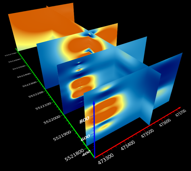
An image slice creates a planar image of the 3D grid at the specified position and rotation. Multiple image planes can be used to create a fence diagram.
Select a 3D grid volume in the Contents window and click 3D View | Add to 3D Grid | Image Slice to create an image slice.

|
| An image slice creates a planar image of the 3D grid in the 3D view. When combined the slices form a fence diagram. |
Image Slice Properties

|
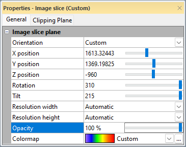
| Set the image plane position and appearance in the Properties window. |
Orientation
Select XY, XZ, or YZ in the Orientation field to quickly set the image slice orientation to one of the axis planes. Otherwise, select Custom to fully define the image slice position and orientation.
Position
The X/Y/Z position properties control the position of the image slice. Type coordinate values or use the slider to set the image slice position. Only one position property is displayed when an axis plane is used. All three coordinate positions are available when a Custom orientation is used.
Rotation and Tilt
When using a Custom orientation, you can modify the Rotation and Tilt properties.
- Positive Rotation values move the plane counterclockwise about the Z axis. Tilt must be greater than or less than zero for Rotation to affect the image slice.
- Positive Tilt values move the plane clockwise about the Y axis.
- When Rotation and Tilt are both equal to zero, the orientation matches the XY plane.
- When Rotation and Tilt both equal to 90, the orientation matches the XZ plane.
- When Rotation is equal to 0 and Tilt is equal to 90, the orientation matches the YZ plane.
Resolution
The Resolution width and Resolution height properties control the appearance of the image slice by determining the total number of pixels used to display the slice. The Resolution width is the number of pixels used to render the image slice along one side. The Resolution height is the number of pixels used to render the image slice along the adjacent side. The directions of the Resolution width and Resolution height vary depending on the shape and angle of the intersection with the 3D volume.
The Resolution width and Resolution height can be specified independently to account for different image slices. For image slices that are generally square, the Resolution width and Resolution height should be set to the same value. For image slices that are rectangular, i.e. one side is significantly longer than the other, the texture appearance may be improved by increasing the resolution along the long side of the image slice.
By default the Resolution width and Resolution height are set to automatic. When both Resolution width and Resolution height are set to Automatic, the image slice resolution along the longer direction is set to 1024 and the image slice resolution along the shorter side is set based on the ratio between the image width and height. For example, a square image will have 1024 pixels along the width and height while a long and skinny image may only use 256 pixels along the shorter direction. When only one of the Resolution width or Resolution height values are set to Automatic, the Automatic value varies based on the specified value and the ratio between the surface width and height.
Opacity
The Opacity property sets the opacity for the entire image slice. 100% is fully opaque. 0% is fully transparent. Overall opacity can also vary due to the specified Colormap. For example, if the Colormap uses a 0 to 100% ramp and the Opacity property is set to 50%, the image slice will appear to ramp from 0% to 50% opaque.
Colormap
Specify the colormap for the image slice in the Colormap field. Select a predefined colormap from the list or click the  button to modify the colormap in the Colormap Editor. The image slice is created using the same colormap as the Volume Render by default.