3D View Environment Lighting Properties
The Lighting page controls the lighting for the entire multi-layer map. This includes the surface, any overlays that may have been combined with the surface, and point vector data in 3D. The light source is fixed relative to the surface, so if the surface is rotated, the light rotates with it.
To edit the Lighting in the 3D View, click Environment in the Contents window. Changes made to the environment lighting will be automatically applied to the lighting of all 3D model objects in the 3D view.
Hill and Reflectance Shading in the 3D View
The 3D view lighting is turned off when the map in the 3D view contains a hill shaded or reflectance shaded color relief layer. This is because the map is already shaded by hill shading or reflectance. The cumulative effect of both lighting systems would result in very dark regions of the map in the 3D view.
To use the 3D view Lighting properties instead of the color relief hill or reflectance shading, the Terrain representation option on the color relief layer General page must be set to Color only.
Lighting Properties
The following properties control the lighting of the model in the 3D view.
|
|
|
Set the lighting for the 3D View environment in the Properties window on the Lighting page. |
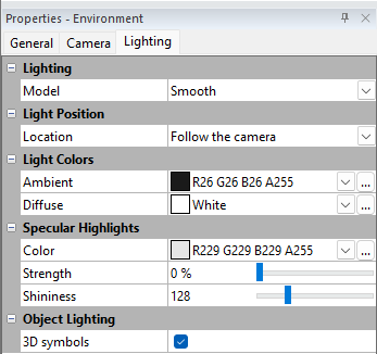
Lighting
Model
To change the lighting, click the current lighting option displayed next to the Model field. Then, select the lighting you want from the three choices provided.
-
None disables all lighting effects. The color shown is from the surface material color only.
-
Smooth splits each grid cell is into two triangular polygons. Gouraud shading is used to interpolate colors within the triangles from the three vertices of each triangle. This results in smooth transitions across the triangles and the entire grid, but it is slightly slower than flat shading.
-
Flat uses a single vertex (grid node) to define the shaded color for the entire polygon. Note that each grid cell is divided into two triangular polygons. This results in a faceted look since each triangle is only filled with a single color.
Location
There are two lighting location options. Click on the current location option to select the desired option
-
Follow the camera updates the light position as your rotate or tilt the model so it always shines directly into the center of the view. This ensures the model is always lit regardless of the position of the camera. Follow the camera is the default setting for a new 3D model.
-
Fixed sets the light source position using Horizontal and Vertical degrees. The light position does not change when the model is rotated or tilted which can result in views that appear completely black or unlit.
-
When the Fixed location is selected, the Horizontal (degrees) and Vertical (degrees) properties are exposed.
-
Light Sources
Source
Select the light source to display in the Light Source #: section.
Add source
The Add source field is used to add light sources. Click "Add" to add a source (up to a maximum of four total). When you've reached the maximum of four light sources, the Add Source option disappears, and you'll only see the Remove Source options.
Remove source
The Remove Source field lets you delete added light sources. This option is displayed for every source you add, with the exception of Source 1. When you've reached the maximum of four light sources, the Add Source option disappears, and you'll only see the Remove Source options.
Light Source #:
The options for the light selected in the Source field of the Light Sources section.
Light Type
-
Directional Light : This type of light simulates a distant light source, such as the sun. You control the direction of the light using azimuth and altitude settings.
-
Point Light : A point light radiates light outward in all directions from a specific point in your 3D scene. You define the location of this point light source using X, Y, and Z coordinates
Light direction | Light Type - Direction
-
Azimuth° = Range is 0-360°. the azimuth of the light source, in compass direction, so degrees (0°=north, 90°=east, 180°=south, 270°=west). This is almost, but not quite, the same as the previous command Horizontal (degrees), which was 0=east and 90=north. If you open up an older SRF file in v30 the light position will be in the same location, but the azimuth value will be adjusted from the original horizontal value.
-
Altitude° = Range is 0-360°. the zenith of the light source, in degrees (0=ground level, 90=directly overhead, 180=the opposite side, 270=directly downward). This is the same as the previous command Vertical (degrees).
Light location | Light Type - Point
-
X = the X coordinate of the light source.
-
Y = the Y coordinate of the light source.
-
Z = the Z coordinate of the light source
-
Note: The sliders for the XYZ coordinates allow the light’s point to be within a box around the map with 50% extra space on all sides (e.g. if the map’s X ranges from 100 to 200, the light can have an X coordinate from 50 to 250).
Light Color
Diffuse refers to light coming from a particular direction and is brighter if aimed directly down on a surface than barely glancing off the surface. When diffuse light hits the surface, it is scattered uniformly in all directions so that it appears equally bright no matter where the eye is located. Increasing diffuse light intensifies shadow effects. The default Diffuse color is white, which is the maximum amount of reflectivity.
Specular Highlights
Specular light come from a particular direction, and tends to bounce off the surface in a preferred direction. A shiny surface such as metal has a high specular component, while a surface like carpet has almost no specular component. Increasing the percentage of specular light results in strong shadow effects and more pronounced "shiny" or glare spots.
-
The default specular highlights Color is light gray. This defines the color of the light when it reflects off the surface.
-
Strength defines how much specular light to show. A strength of 0% will not show any specular light and a strength of 100% will show specular light at full strength. Type a new value or click and drag the
 to the desired strength value.
 -
Shininess defines how reflective or shiny the surface material is. A shininess value of 0 will not reflect any light. There is no upper limit to the shininess of a surface. To enter a value greater than the default slider maximum of 500, simply type it into the text field.
Ambient Color
The Ambient field affects all light sources, and refers to light that has been scattered so evenly by the environment that its direction is impossible to determine. Increasing the ambient light component brightens the scene without casting shadows. The default Ambient color is 90% black which means that the ambient light contribution is fairly small.
Note on Light Colors
In general, these reflectivity colors should be specified as shades of gray in order to evenly reflect the surface material color components. However, special effects are possible by specifying non-gray colors for the reflectivity. For example, assume the Ambient reflectivity is set to pure red, and the Diffuse and Specular Highlights colors are set to pure black. The Diffuse and Specular components are essentially disabled by setting their reflectivity color to black. The only light that is reflected to the viewer is red ambient light. Portions of the surface that lack a red component in the material color will appear black, since only red light is reflected to the viewer.
Object Lighting
The 3D Symbols property is selected by default to enable the lighting to illuminate and cast shadows on point vector data as it does on the surface displayed in the 3D View window. When this property is cleared, shadows on 3D symbols remain static. The Symbol method for 3D vector point data must be set to Symbols and the symbol style either Shaded Circle, Sphere or Cube. The lighting Model must be either Smooth or Flat.