Grid Transform
The Grids | Calculate | Transform command contains several options that modify the X and Y map coordinates of grid nodes within the grid file. It does not alter the Z values. The Transform options are used to shift, scale, rotate, or mirror grid nodes within a grid file.
The Grid Transform Dialog
Click the Grids | Calculate | Transform command or the ![]() button to open the Grid Transform dialog.
button to open the Grid Transform dialog.
|
|
|
Specify grid transform options in the Grid Transform dialog. |
Input Grid
Specify the source map layer or grid file in the Input Grid section. Click the current selection and select a map layer from the list. Only map layers created from grid files are included in the Input Grid list. Click Browse to load a grid file with the Open Grid dialog.
Operation
The Operation list controls the transformation type. Click on the box or drop-down arrow and select an option from the list.
|
The Offset option adds or subtracts a number from the X and Y dimensions. Specify the Offset option from the Operation list, and specify the amount of the offset in the X Offset and Y Offset boxes in positive or negative units. For example, if the input grid ranges are X: 1 to 9 and Y: 2 to 8, and the offsets are 10.0 for both the X Offset and Y Offset, then the output grid ranges will be X: 11 to 19 and Y: 12 to 18. |
|
|
Scale |
The Scale option multiplies the X and Y ranges by a factor. Specify the Scale option from the Operation list, and specify the scaling factors in the X Scale and Y Scale boxes displayed in the Grid Transform dialog. The scaling origin is the lower left corner of the grid, so only the xMax and yMax values are changed. For example, if the input grid ranges are X: 1 to 9 and Y: 2 to 8 and the X Scale and Y Scale factors are both 3.0, then the output grid ranges will be X: 1 to 25 (((9 - 1) x 3.0) + 1) and Y: 2 to 20 (((8 - 2) x 3.0) + 2). |
|
Rotate |
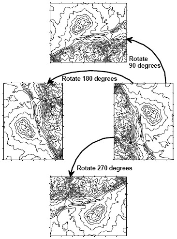
The Rotate option rotates a grid in multiples of 90 degrees (0, 90, 180, 270, …). Select the Rotate option in the Operation list, and specify the rotation angle in the Angle box. The origin of the map remains in the lower left, and the axes continue to increase in the same direction, with the X axis increasing to the right, and the Y axis increasing upwards.
The Rotate option rotates the grid in multiples of 90 degrees without changing the XY origin. |
|
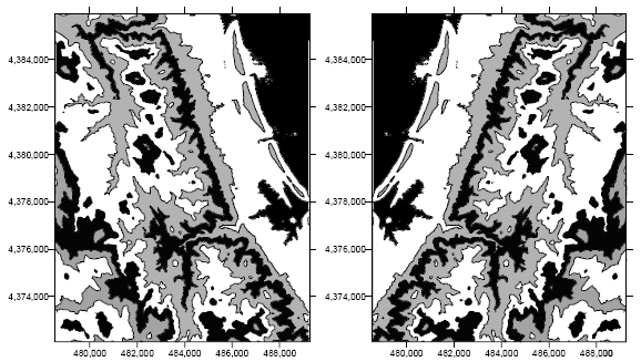
The Mirror X option creates a new grid file with the order of the grid nodes reversed in the X direction. The output grid file uses the same minimum and maximum X and Y coordinates as the input grid file. The origin of the grid remains in the lower left corner, with X increasing to the right and Y increasing upward. The Y order remains unchanged.
The Mirror X option creates a mirror image of the grid file with the X order reversed. |
|
|
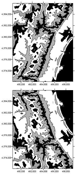
The Mirror Y option creates a new grid file with the order of the grid nodes reversed in the Y direction. The output grid file uses the same minimum and maximum X and Y coordinates as the input grid file. The origin of the grid remains in the lower left corner, with X increasing to the right and Y increasing upward. The X order remains unchanged.
The Mirror Y option creates a mirror image of the grid file with the Y order reversed. |
Output Grid
Type a file path and file name, including the file type extension, in the Output Grid field, or click the ![]() button and specify the path and file name for the grid file in the Save Grid As dialog.
button and specify the path and file name for the grid file in the Save Grid As dialog.
Add New Map or Layer
Check the Add grid as layer to check box to automatically add the created grid to a new or existing map. Select [New Map] in the Add grid as layer to field to create a new map. Click the current selection and select an existing map to add a new layer to the map. Select the layer type by clicking the current selection in the New layer type field and selecting the desired layer type from the list.
Note: If you are saving the grid file in the DEM grid format, clear the Add grid as layer check box and add the map or layer with a Home | New Map or Home | Add to Map | Layer command.
To Transform a Grid File
- Click the Grids | Calculate | Transform command or the
 button.
 - In the Open Grid dialog, select a grid file to transform and click Open.
- In the Grid Transform dialog, choose an Operation and any associated options.
- Click the
 button to display the Save Grid As dialog.
 - In the Save as type list, select the format for the output file. nter the path and File name for the transformed grid. Click Save to return to the Grid Transform dialog.
- Click OK to create the transformed file.
Grid Transform and .GSR2 Files
When the input .GRD file for a Grid | Transform command has a defined .GSR2 file with coordinate system information, this information is used for the output .GRD file. The Export Options dialog appears with the option to save the coordinate system information. It is recommended to check the GS Reference (Version 2) file if you intend to use the grid file in Surfer, as the GSR2 retains all of the information needed. The grid has the same coordinate system as the original file, but the .GSR2 is required to define the coordinate system.