Volumes and Areas
The Grids | Calculate | Volume command calculates net volumes, cut and fill volumes, planar areas, and surface areas. Computational results are systematically compiled and output directly to the standalone Grid Volume Report.
Grid Volume Dialog Options
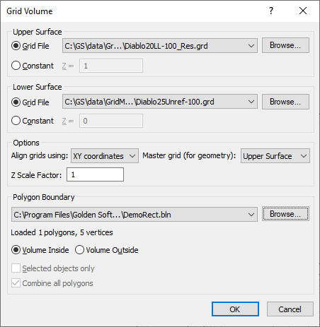
Execute the Grids | Calculate | Volume command to open the Grid Volume dialog and configure the calculations parameters.
|
|
|
Specify grid volume options in the Grid Volume dialog. |
Upper Surface and Lower Surface Boundaries
Define the bounding vertical extents of the mathematical solid within the Upper Surface and Lower Surface sections. Surfaces can be generated from grid files or designated as constant planar fields.
Grid File Source
The Grid File option sets a surface from an active map layer or an external grid file (.GRD). Only layers generated from grid files are available within the map selection menu. Click Browse to populate this field using an external file via the Open Grid dialog.
Constant Z Value
The Constant option defines a completely uniform flat planar surface datum. Input the desired elevation level directly into the Z = field using native vertical Z data units.
Spatial Grid Alignment Rules
If the input upper and lower surface grid files contain matching row and column matrices, select Node position from the Align grids using list. Calculations are performed across equivalent grid node indices independent of explicit spatial coordinates. If the inputs feature varying dimensions or resolutions, select XY coordinates to force Surfer to match nodes in georeferenced space.
When aligned by XY coordinates across varying referenced coordinate systems, the calculations adapt the projection settings of the specified master data sheet. If unreferenced and referenced grids are mixed, a system warning is displayed. Selecting Yes bypasses the warning and continues calculations without projecting the unreferenced grid layer. Selecting No terminates the process, allowing users to safely assign a uniform coordinate space via Grids | Edit | Assign Coordinate System.
Master Grid Selection
When aligning data via spatial coordinates, select either the Upper Surface or Lower Surface from the Master grid (for geometry) menu to serve as the baseline resolution, geometry, and extent envelope for the calculation.
Z Scale Factor Normalization
If the horizontal projection axes (X,Y) and vertical tracking axis (Z) utilize non-homogeneous units (e.g., horizontal meters versus vertical feet), raw volume outputs represent meaningless mixed dimensions. Apply an exact multiplicative scaling conversion factor in the Z Scale Factor field to establish cubic unit uniformity. For example, adjusting the factor to 0.3048 scales vertical feet cleanly into cubic meters.
-
Where X, Y, and Z units are identical in feet, results render uniformly in cubic feet (ft3).
Polygon Boundary Clipping
Isolate volumetric computations inside or outside an explicit vector area by defining a Polygon Boundary layer or external vector file. If the boundary target file features multiple discrete polygons, calculations aggregate across all valid shapes. Bounding geometry parameters are dynamically logged beneath the selection interface.
The following vector spatial file formats are actively supported:
Volume Inside / Volume Outside Filter Mode
Select Volume Inside to limit mass integration constraints strictly within the defined polygon vertices. Select Volume Outside to invert the selection mask, calculating all available space outside the defined line boundary.
Selected Objects Only Filter
Check the Selected objects only checkbox to isolate operations exclusively to highlighted geometric elements within an active base map layer. Bounding counts automatically update upon initialization. This operation parameter is restricted to plot document selections and cannot be applied directly to unmapped source vector files. Elements must be selected prior to running the volume execution command.
Combine All Polygons Matrix Mode
Enable Combine all polygons to combine spatial statistics into a singular master total when processing intricate multi-polygon boundaries. If unchecked, the engine isolates calculations for each unique shape profile, outputting clean individual itemized statistics inside the final report.
Mathematical Modeling and Resolution Controls
Volumetric calculations track the absolute distance between your bounding sheets as an aligned array of three-dimensional columns. Bounding limits pass through specified functional grid node values or constant planes. NoData regions mapped across either dataset are dropped from mathematical integration blocks to ensure accuracy.
Grid Resolution and Mathematical Approximation Error
Surfer evaluates total volume cell-by-cell across the structural grid matrix. In spaces where a bounding surface features pitch or slope variations at a cell boundary edge, the software executes numerical approximations to define the top or bottom prism termination cap.
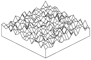
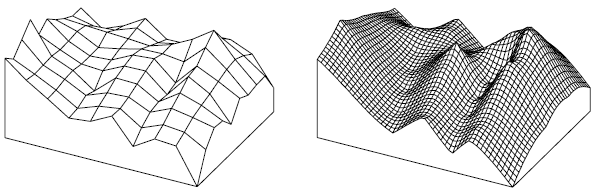
Coarse grid matrices feature larger terminal prisms, which can inject significant mathematical approximation noise into your data. Volumetric precision scales non-linearly as grid resolution is enhanced, because smaller cell spacing forces a reduction in terminal prism sizes relative to total vertical column arrays. Consequently, choppy, irregular, or noisy data surfaces are poor integration candidates and should be refined before processing.
Grid Resolution Comparison Examples
|
|
|
This grid has a highly irregular surface and is a poor candidate for accurate volume calculations. |
|
|
|
These two grids are based on the same source data but generated using completely different grid cell densities. The dense matrix structure shown on the right produces a significantly more precise, accurate volumetric output. |
See Also
Introduction to Volumes, Areas, Cross Sections
Calculating the Volume of a Lake
Calculating the Volume of a Grid with NoData values