Grid Filter
The Grids | Edit | Filter command applies methods of digital image analysis to grids. This includes a broad suite of smoothing (low-pass) filters, as well as contrast enhancement filters, edge enhancement filters, edge detection filters, general high-pass filters, etc. Surfer also includes the capability for user-defined, general linear filters.
The Neighborhood
When filtering a grid, each node of the output grid is computed as a function of the corresponding node, and its neighbors, in the input grid. The concept of the neighborhood is used in grid filtering. The neighborhood of an output grid node is a rectangular sub-array of nodes in the input grid that is centered on the corresponding input grid node. A neighborhood has a non-zero width, and a non-zero height. Since the neighborhood is centered on a node, the width and height must both be odd numbers. For example, if the width and the height of the neighborhood are both three, the neighborhood of the output grid node at (21, 35) is the following rectangular sub-array of input grid nodes:
(20, 36) (21, 36) (22, 36)
(20, 35) (21, 35) (22, 35)
(20, 34) (21, 34) (22, 34)
If the height of the neighborhood is represented by S and the width of the neighborhood is represented by T, then the number of nodes in the neighborhood equals S ×. Furthermore, the nodes in the neighborhood can be enumerated as:
|
|
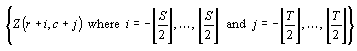
where ![]() is the largest integer less than or equal to A.
is the largest integer less than or equal to A.
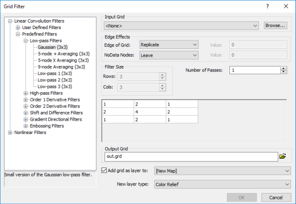
The box in the lower-right part of the dialog displays the neighborhood size, based on the number of Rows and Cols, along with the weights for each grid node in the neighborhood. Each element of the matrix is used to weight the grid node that lies “below” it. The products are then summed, normalized, and assigned to the value below the center node. The filter is then “moved” to the next node and the process is repeated until all nodes have been processed.
Grid Filter Dialog
Click the Grids | Edit | Filter command or the  button to open the Grid Filter dialog.
|
|
|
Specify filtering options in the Grid Filter dialog. |
Filter Categories
There are two main categories of filters: Linear Convolution Filters and Nonlinear Filters. Both of these general types are real space filtering methods.
Input Grid
Specify the source map layer or grid file in the Input Grid section. Click the current selection and select a map layer from the list. Only map layers created from grid files are included in the Input Grid list. Click Browse to load a grid file with the Open Grid dialog.
Edge Effects
There are two settings for edge effects, how to calculate the Edge of Grid nodes and how to calculate neighborhoods with NoData Nodes.
Filter Size
Filter Size is available with user-defined linear convolution filters and some nonlinear filters. You can use Filter Size to determine the size of the neighborhood.
Number of Passes
Set the number of times the filter is applied with the Number of Passes box.
Output Grid
Digital filtering computes each node of the output grid as a function of the corresponding node, and its neighbors, of the input grid. Choose a path and file name for the grid in the Output Grid section. Type a file path and file name, including the file type extension, in the Output Grid field, or click the ![]() button and specify the path and file name for the grid file in the Save Grid As dialog.
button and specify the path and file name for the grid file in the Save Grid As dialog.
Add New Map or Layer
Check the Add grid as layer to check box to automatically add the created grid to a new or existing map. Select [New Map] in the Add grid as layer to field to create a new map. Click the current selection and select an existing map to add a new layer to the map. Select the layer type by clicking the current selection in the New layer type field and selecting the desired layer type from the list.
Note: If you are saving the grid file in the DEM grid format, clear the Add grid as layer check box and add the map or layer with a Home | New Map or Home | Add to Map | Layer command.
Grid Filter and .GSR2 Files
When the input .GRD file for a Grids | Edit | Filter command has a defined .GSR2 file with coordinate system information, this information is used for the output .GRD file. The Export Options dialog appears with the option to save the coordinate system information. It is recommended to check the GS Reference (Version 2) file if you intend to use the grid file in Surfer, as the GSR2 retains all of the information needed. The grid has the same coordinate system as the original file, but the .GSR2 is required to define the coordinate system automatically.