.DWG File Description
Surfer can import and export .DWG files. AutoCAD .DWG files are ASCII files (i.e., they can be edited with a text editor, word processor, or worksheet) or binary files (cannot be edited) containing records indicating graphical entities and their attributes. They provide a medium of exchange with AutoDesk's AutoCAD program. The format of .DWG files is complex and a detailed discussion is beyond the scope of this Help file. Many books describing the .DWG file format are widely available.
File Description
The .DWG file format is a native design file used by architects and engineers for drafting and modeling. Surfer provides full functionality for both importing and exporting .DWG files, allowing you to easily share and integrate data within CAD-based workflows.
See the AutoCAD DXF File Description for information on DXF files.
Graphics
Graphical information may be stored in the AutoCAD Drawing Exchange Format (.DWG). Many programs, including AutoDesk Inc.'s AutoCAD (Computer Aided Design) program can import .DWG files, allowing one to display and/or further manipulate the images. Surfer supports MTEXT (multi-line text block) background color in .DWG import filter.
DWG files contain graphical entities (lines, polygons, etc.) and their attributes. When imported, these entities can be used to display or further manipulate map images.
3DSOLID is a proprietary format, and 3DSOLID entities are not supported in Surfer. If the .DWG file contains 3DSOLID objects, the 3DSOLID objects will be omitted from the import.
Data
Surfer supports both the graphical and data components of .DWG files. AutoCAD .DWG files can contain point data that includes X, Y, and Z data. DWG files can be opened in a worksheet, used for gridding, or used for post map or classed post map display.
.DWG files often contain Z values that define the vertical dimension of features, which is common for contour maps or 3D models. When the DWG file is opened in the worksheet, the X and Y coordinates are displayed in columns A and B. If the DWG file contains Z values, the Z values are displayed in column C. If no Z value is included, column C contains a zero (0). When used for post map, classed post map, and gridding, the X, Y, and Z (if any) are automatically read into the appropriate locations.To view these values in Surfer, select a feature (e.g., polyline or polygon) in the imported base layer and check the ZLEVEL field under Properties | Info | Attributes.
Importing .DWG Files
You can import .DWG files into Surfer using one of the methods below. Please note, when importing a DWG file and choosing to import layers into separate base layers, Surfer will skip any empty layers within the source file.
-
Drag and drop the file directly into the application.
-
Use the File | Open command to open the file in the worksheet.
-
Use the Home | New Map | Base | Base or Home | New Map | Contour commands to create a new map layer.
Drawing Import Options Dialog
When a .DWG file is imported, the Drawing Import Options dialog appears, allowing you to customize the import settings.
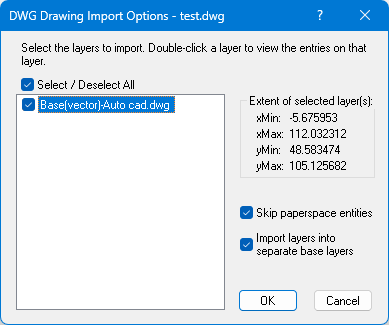
DWG Import Options window.
-
Import selected layer(s): This section allows you to choose which layers from the .DWG file will be imported. This is useful for troubleshooting complex or improperly scaled files.
-
Extent of selected layer(s): This window dynamically updates to show the calculated map limits based on the layers currently checked for importation. This helps you confirm the intended size of the imported map before completing the process.
-
Skip paperspace entities: This option is checked by default. Checking this ensures that only geometry created in AutoCAD's Modelspace (full-scale geometry) is imported, excluding elements designed for layout and printing.
-
Import layers into separate base layers: This option is checked by default.
-
Checked: Each selected layer from the .DWG is imported as its own base layer, retaining the original name with Base(vector) appended.
-
Unchecked: All selected layers are combined into a single base layer.
-
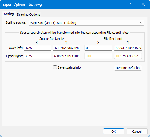
Exporting to .DWG Files
Surfer also allows you to export your files to the native .DWG format. This can be done via the File | Export command or by saving 3D vector data using the 3D View | Output | Save Vector Data command.
The export process opens a dialog with two tabs for customization:
-
Scaling: This tab contains the same scaling options found when exporting to the .DXF format.
-
Drawing Options: This tab includes default settings similar to .DXF export, and features an updated File Compatibility dropdown menu that shows the most recent ODA supported versions of the AutoCAD .DWG file format.
DWG Export Options window
Drawing Options
File Compatibility
Select the appropriate file compatibility. Available options are AutoCAD 2018, AutoCAD 2013, AutoCAD 2010, and AutoCAD 2007.
File Format
Choose Text (ASCII) or Binary to specify the format of the exported DWG file. See the AutoCAD DXF File Description for information on the organization of DXF files.
General Export Options
The following export options pertain to the objects within the DWG file.
All Lines Same Color
Choose All lines same color if you don't want an AutoCAD color number (1-255) assigned to each of your lines. The default color for the layer will be used instead. All exported graphical entities are assigned to a layer named GSLAYER.
All Lines Same Style
Choose All lines same style if you want exported lines to be assigned the default style (for the GSLAYER) when imported into AutoCAD. Otherwise, exported lines will retain their style (solid, dashed, etc.).
All Lines Same Width
Choose All lines same width if you want exported lines to be assigned the default width (for the GSLAYER) when imported into AutoCAD. Otherwise, exported lines will be the width assigned in the application document.
All Text As Areas
If the (All text as areas) box is unchecked, text is exported as editable AutoCAD text entities, but all fonts are converted to AutoCAD's STANDARD font. Once the file is inside AutoCAD, the text entities can be edited in the normal AutoCAD fashion. Also note that while size and orientation are usually maintained, text will be converted to solid polygons if there's any shear (text slanted or not perpendicular to the text baseline), perspective (when the height of glyphs in the text string are not all the same or with text appearing in 3D), or clipping (text partially outside the map limits).
Checking the All Text as Areas box exports all text as DWG solid polygons, guaranteeing correct orientation. Whether or not these solid polygons (like all solid polygons) will be filled or not is controlled by the Fill solid areas option (see below).
Fill Solid Areas
Choose Fill solid areas if you want the interior of solid areas (polygons) to be filled. Otherwise, the areas will be exported as AutoCAD CLOSED POLYLINE entities.
Render Marker Symbols
Check the Render marker symbols check box if the marker symbols should be exported to the DWG file. The marker symbols are exported as lines and polygons. When the Render marker symbols option is not checked, marker symbols are exported to the DWG file as points.
Use ONLY Spatial Information
Choose Use ONLY spatial information if you want to export only spatial information and not object attributes or text labels. Spatial information is only concerned with the location of objects in space (i.e., their coordinates) and not with their attributes (such as line or fill style, marker symbol used, text labels, etc.) For example, if this option is chosen, all text will be ignored, markers will be exported as point entities instead of polygonal glyphs and coordinates output to the DWG file will be stored in map units instead of inches. This is useful when exporting base maps when only the spatial information is desired.
The AutoCAD program's behavior when importing DWG files (via the DWG IN command) is different depending on whether the AutoCAD drawing file [.DRW] is brand new or already contains drawing entities. If the file is brand new, attributes (such as line style) are loaded from the Tables section, so lines encountered in the Entities section will have the proper line style (solid, dash, dash-dot, etc.). However, if an old drawing file is already open, AutoCAD will ignore the Tables section and only read the Entities section. If the DWG file contains lines with styles not already defined, AutoCAD will issue an error message and abort the DWG import. It is recommended you choose the All lines same style option when exporting DWG files that will be imported into existing AutoCAD drawings. AutoCAD will then assign the default style to all lines in the imported layer (named GSLAYER).
Write LWPOLYLINE entities even when 3D data is availible
By default the Write LWPOLYLINE entities even when 3D data is available check box is not checked. Check the Write LWPOLYLINE entities even when 3D data is available check box to export all lines as 2D LWPOLYLINE entities. Z values will be written as ZLEVEL attributes when Write Z data is checked; no Z values will be written when Write Z data is cleared. Line properties will be saved.
Leave the Write LWPOLYLINE entities even when 3D data is available check box cleared to export 3D objects as 3D POLYLINE entities and 2D objects as LWPOLYLINE entities. The Write Z data check box is checked but not available to change, indicating that Z values will be written as attributes when available. 3D POLYLINE objects do not support line properties.
Use the File | Export command with the Write LWPOLYLINE entities even when 3D data is available export option cleared to export the contours as POLYLINE entities with the Z values written for each vertex. Use the File | Export command with the Write LWPOLYLINE entities even when 3D data is available export option checked to export the contours as LWPOLYLINE entities with the Z values as an attribute for each line.
Resize embedded images to less than [ ] (MB)
The Resize embedded images to less than option specifies the maximum size (in megabytes) an embedded image is allowed to be. If an exported image exceeds this size, its resolution will be reduced so it doesn’t exceed the designated maximum size. Increase this value to get better looking images at the expense of larger export files.
Defaults
The Defaults button sets all buttons and check boxes to default conditions.
See Also
Export Options - Spatial References
AutoCAD DWG Export Options Dialog
AutoCAD DWG Import Options Dialog