Reshape
Click the Features | Edit Features | Reshape command or the  button to move, add, and delete vertices within a selected polyline, polygon, 3D polyline, 3D polygon, or spline polyline. Objects such as metafiles, composites, base maps, polygons, polylines, 3D polylines and 3D polygons can be edited with Reshape.
Entering Reshape Mode
Click the Features | Edit Features | Reshape command to enter the reshape mode. Alternatively, you can right-click on the object and click Reshape. After selecting Reshape, the cursor will change to ![]() to indicate reshape mode. When you select an object that can be reshaped (a polyline, spline polyline, or polygon), all the vertices in the selected object are shown with hollow squares. Reshape mode is persistent and you can reshape multiple items until you exit the reshape mode. After you reshape an object, select another object to reshape, or exit reshape mode.
to indicate reshape mode. When you select an object that can be reshaped (a polyline, spline polyline, or polygon), all the vertices in the selected object are shown with hollow squares. Reshape mode is persistent and you can reshape multiple items until you exit the reshape mode. After you reshape an object, select another object to reshape, or exit reshape mode.
Exiting Reshape Mode
To exit reshape mode, press the ESC key on the keyboard. Alternatively, select another command mode.
Select Vertices
- Left-click on a vertex to select it. The selected vertex is indicated by a solid green square.
- To select the first vertex, press the HOME key. To select the last vertex, press the END key.
- To shift the selected vertices forward by one position, press the TAB key. To shift the selected vertices backward by one position, hold the SHIFT key and press the TAB key.
- To select multiple vertices, hold down the SHIFT key and left-click additional vertices or left-click and drag the cursor to make a rectangular block selection. Vertices can be added or removed from the block selected vertices by holding down the SHIFT key.
- Hovering the mouse over an unselected vertex will display a grey highlight around the vertex indicating it may be selected or dragged.
- The cursor will change to a
 when it is over a vertex to indicate the vertex may be selected or dragged.
 - If you have multiple polyline or polygon objects in the plot window, you can edit multiple objects while in the reshape mode. Vertices can only be edited for the selected object.
Move Vertices
Once a vertex or vertices are selected and the cursor display is a ![]() , hold the left mouse button and drag the vertex to a new location. Release the left mouse button to place the vertex in the new location.
, hold the left mouse button and drag the vertex to a new location. Release the left mouse button to place the vertex in the new location.
|
|
|
|
|
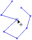
Enter reshape mode and select a vertex. |
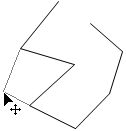
Drag the vertex to a new location. The original line is displayed in addition to the new line that will connect to the new vertex position. |
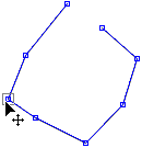
Release the mouse button and the vertex is moved. |
Alternatively, place the cursor over the vertex, hold the SPACEBAR, and use the ARROW keys on the keyboard to move the vertex to a new location.
Deselect Vertices
- A selected vertex can be deselected by holding down the SHIFT key and left-clicking the vertex.
- All vertices can be deselected by clicking in an unused space.
- Pressing ESC while dragging will cancel the drag. Pressing ESC while NOT dragging will exit the reshape tool.
- Each individual edit can be undone using the Undo command.
Add Vertices
To enter insert mode, hold down the CTRL key. The cursor will change to . Left-click anywhere in the plot window, or on the existing object and a new node will be added at the closest point on the existing object.
Remove Vertices
Select a vertex or multiple vertices with one of the methods outlined above. Press DELETE to remove the selected vertex/vertices, and the next vertex in the object is selected. You can hold DELETE to remove contiguous vertices as the selection moves throughout the object. Degenerate polylines (one-point polylines) and degenerate polygons (one- or two-point polygons) can be created by removing vertices. The objected can be deleted by removing all of the vertices. However, spline polylines are deleted when there are fewer than two knot vertices.
Status Bar
When the reshape tool is active, the status bar updates with current position in world coordinates and map coordinates (if available).
To edit a polyline, polygon, 3D polyline or 3D polygon
- Select the object.
- Click the Features | Edit Features | Reshape command.
- The arrow pointer turns into an arrowhead pointer and all the vertices appear as small hollow squares.
- To move a vertex, left-click on the vertex with the mouse and drag it to a new location. To add a vertex, hold down the CTRL key and click the area on the polygon or polyline. To delete a vertex, select it and then press the DELETE key.
- After reshaping the object, press the ESC key to exit edit mode.
To edit a spline polyline
- Select the spline polyline in the Contents window or the plot window by clicking on it.
- Click the Features | Edit Features | Reshape command to enter editing mode.
- Anchor points appear as white boxes on the spline polyline. Click on an anchor point to select it.
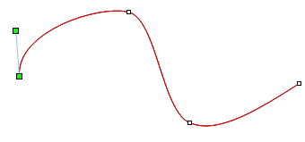
- For anchor points that are the first or last point on the spline polyline, two control points will be active. The control point that is located at the exact anchor point controls the position of the anchor point. Click and drag the green control point to a new location to move the line. The control point that is connected by a line to the anchor point controls the degree of curvature of the line. Click and drag the green control point to make the line more or less curvy. The closer the control point is to the line, the straighter the line will be.
|
|
|
The end anchor point is being edited. The top green control point controls the curvature of the spline polyline. The bottom green control point controls the location of the anchor point. |
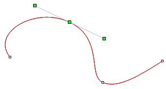
- For anchor points that are not the first or last point on the spline polyline, three control points will be active for each anchor point. The three control points are connected by a light blue line. The middle control point determines the location of the anchor point. The two outer control points determine the curvature of the line. Click the outer control points and drag to a new location to make the line more or less curvy. The line connecting the control points will always be tangent to the anchor point on the spline polyline. The shorter the connecting line, the sharper the angle at the anchor point. The longer the connecting line, the smoother the curve at the anchor point.
|
|
|
A middle anchor point is being edited. The left and right green control points control the curvature of the spline polyline. The center green control point determines the location of the anchor point. |
- To add points to the spline polyline, hold down the CTRL key and click on the line. A new control point is added.
- To delete points, click on an existing point and press the DELETE key on the keyboard.
The contents of all map layers are always constrained within the map limits. If an object exceeds the map limits, the object is clipped. Change the map limits to expand the map limits to include reshaped contents. Check the Use data limits box to resize the map limits to fit your edited object.