CLR Color Spectrum File Format
Color spectrum files, with a .CLR extension, define a spectrum or continuous gradation of colors. This is achieved by using a series of anchor points, each assigned a specific color. The colors between these anchor points are interpolated to create a smooth transition, as specified by the file.
The current version of the .CLR file format is version 3, which has superseded versions 1 and 2. While each version has a slightly different internal structure, they are all based on the same fundamental format.
File Format
The .CLR format is an ASCII text file with a header on the first line. Subsequent lines specify the anchor points, with one anchor point per line.
Version 3 CLR files
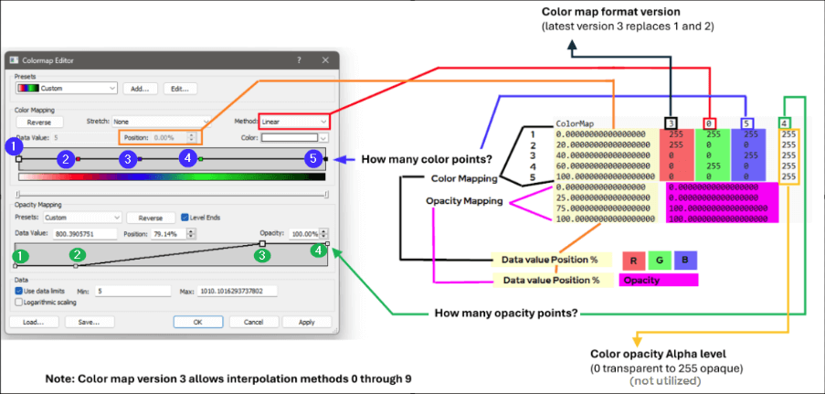
The image below provides a detailed breakdown of the .CLR file format (version 3) and its relationship to the Colormap Editor dialog. It visually connects the settings and controls used in the software interface—including color and opacity anchor nodes—to their corresponding data values within the .CLR file itself.
A breakdown of each part of the CLR file parts can be found in the following sections.
|
CLR Header
The header consists of the following space-delimited fields:
|
Element |
Description |
|
Id |
The case-sensitive string "ColorMap" without the quotes. |
|
Version |
The format version number, which should be set to 1, 2, or 3. |
|
InterpMethod |
The interpolation method, defined by an integer from 0 to 9. |
|
ColorNodes |
The number of color anchor nodes in the CLR file (version 3 only) |
|
OpacityNodes |
The number of opacity anchor nodes in the CLR file (version 3 only) |
Example Header
ColorMap 3 0 3 3
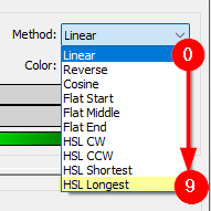
InterpMethod
The InterpMethod (Interpolation Method) is stored as an integer value that represents the selected interpolation method. This value is determined by the method's position in the list within the Colormap Editor, as described below.
|
|
CLR Anchor points
Color anchor points
The lines following the header define the color anchor nodes, with one point per line. Each line contains the following space-delimited fields:
|
Element |
Description |
|
Position |
The floating-point percentage value (from 0.0 to 100.0). The positions must be in increasing order, and both 0 and 100 percent positions must be explicitly included. |
|
Red |
The red color component (0 to 255) |
|
Green |
The green color component (0 to 255) |
|
Blue |
The blue color component (0 to 255) |
|
Alpha |
The opacity component (0 to 255). 0 is fully transparent, and 255 is fully opaque. (version 2 & 3 only) |
Example color anchor point
0.00000000000000000 0 0 255 255
Opacity anchor points
In version 3 .CLR files, a final set of lines defines the opacity anchor nodes, with one point per line. Each line has the following space-delimited fields:
|
Element |
Description |
|
Position |
The floating-point percentage value (from 0.0 to 100.0). As with color points, the positions must be in increasing order, and both 0 and 100 percent positions must be specified. |
|
Opacity |
The opacity is the floating point percentage value from 0.0 to 100.0. |
Example opacity anchor point
0.00000000000000000 78.43000000000000682
Notes on older Version 1 & Version 2 CLR files
The following key differences exist for older file versions:
-
CLR Header
-
The InterpMethod should be set to 1 for versions 1 and 2.
-
The ColorNodes field is not included in the header for Version 1 or 2 files.
-
The OpacityNodes field is not included in the header for Version 1 or 2 files.
-
-
CLR Anchor points
-
The Alpha value is not included in Version 1 color anchor points.
-
Examples
Example 1
This example demonstrates a simple three-anchor-point spectrum. The anchor points are at positions 0, 50, and 100 percent.
-
The zero position is a slightly transparent blue.
-
The 50 percent anchor is mostly transparent green.
-
The 100 percent position is fully opaque yellow.
|
Color Map Version 3 |
Color Map Version 2 |
Color Map Version 1 |
|
ColorMap 3 0 3 3 0.00000000000000000 0 0 255 255 50.00000000000000000 0 255 0 255 100.00000000000000000 255 255 0 255 0.00000000000000000 78.43000000000000682 50.00000000000000000 7.89473684210526283 100.00000000000000000 100.00000000000000000 |
ColorMap 2 1 0.000000 0 0 255 200 50.000000 0 255 0 20 100.000000 255 255 0 255 |
ColorMap 1 1 0 0 0 255 50 0 255 0 100 255 255 0 |
Example 2
It is also possible to have coincident anchor points in a color file. Anchors and colors are interpreted in order from 0 percent to 100 percent. In the case of coincident points, you can create maps with distinct boundaries, similar to the example shown here.
|
Color Map Version 3 |
Color Map Version 2 |
Color Map Version 1 |
|
ColorMap 3 0 4 2 0.00000000000000000 0 0 0 255 50.00000000000000000 0 220 0 255 50.00000000000000000 136 136 0 255 100.00000000000000000 216 0 216 255 0.00000000000000000 100.00000000000000000 100.00000000000000000 100.00000000000000000 |
ColorMap 2 1 0.000000 255 0 0 255 50.000000 255 255 0 255 50.000000 0 0 255 255 100.000000 255 255 255 255 |
Example 3
A popular .CLR file is RAINBOW.CLR. The following example shows the format of RAINBOW.CLR:
|
Color Map Version 1 |
|
ColorMap 1 1 0 153 102 255 20 0 0 255 40 0 255 0 60 255 255 0 80 255 102 0 100 255 0 0 |
More Examples
You can find numerous sample .CLR files on the Golden Software website, available for download as a ZIP file within the Customizing the colormap presets in Surfer article.