Symbology - Classed Symbols
The Classed Symbols symbology adds proportionally sized symbols to the features by class. The features in the base layer are classified by the selected attribute. The symbols for each class can be assigned individually or graduated symbols can be assigned across the classes.
When the Classed Symbols symbology is applied to polygon features, symbols are created in addition to the polygon features. When the Classed Symbols symbology is applied to point features, the point feature symbol properties are controlled by the symbology. Classed Symbols symbology is not applied to polyline features.
|
|
|
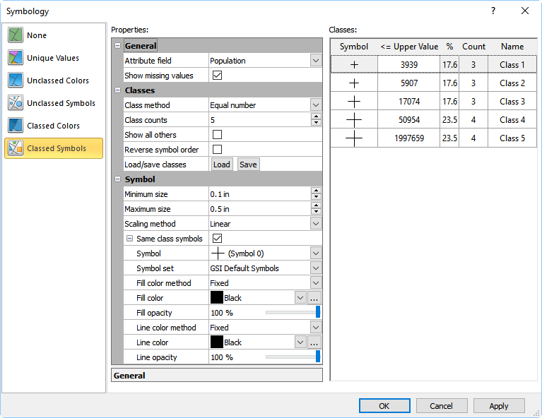
Select Classed Symbols to add symbols to the map by a classified attribute value. |
Properties
The Properties pane includes the properties for selecting the attribute and defining the classes. The Properties pane is in the middle of the Symbology dialog.
Attribute Field
The Attribute field specifies which attribute is used to classify the features in the base layer. Select the desired attribute from the Attribute field list. Only attributes with numeric values are displayed in the Attribute field list when the Classed colors symbology is selected.
The first numeric attribute for the objects in the layer is the default selection in the Attribute field when a symbology is selected for the first time. When a base layer symbology using a numeric attribute is already applied, the Attribute field value is not changed when Classed Symbols is selected. The Attribute field changes to the first numeric attribute for the objects in the layer when Classed Symbols is selected and the base layer is currently using a text attribute for the current symbology.
Show Missing Values
Select the Show missing values option to include any features that do not have an attribute value for the selected Attribute field in the layer. When the Show missing values option is checked, features that do not have an Attribute field value are displayed, and their properties are controlled by the base layer General page, as well as their individual Line, Fill, and/or Symbol properties.
Clear the Show missing values check box to hide the features that do not have an Attribute field value from the base layer. The features will still be visible in the Contents window, but the features will not be included in the base layer in the plot window.
Features that have an Attribute field value outside the class limits are controlled by the Show all others option. When Show all others is cleared, features with an Attribute field value outside the class limits are treated the same as missing values. When Show all others is selected, features with an Attribute field value outside the class limits are controlled by the All others class properties.
Class Method
The Class method specifies the method used to calculate the limits of the classes. There are five options available: Equal number, Equal interval, Natural breaks, Standard deviation, and User defined. To change the Class method, click on the current option and select the desired option from the list.
-
Equal number assigns the class ranges such that approximately equal numbers of features are included in each class. Normally in this case, the interval of each class is different.
-
Equal interval assigns the class ranges so the interval between the minimum and maximum values are equal for each class. Normally in this case, a different number of features is assigned to each class.
-
Natural breaks uses the Fisher-Jenks algorithm to calculate the ideal natural breaks in the data. Typically these natural breaks are ideal beginnings and endings for data classes. The algorithm is based on Fisher's statement that any optimal classification of data consists of the sum of optimal classes of subsets of the data. To learn more about Jenks' natural breaks data classification method, please refer to Slocum, Terry A. Thematic Cartography and Visualization. New Jersey: Prentice-Hall, 1999.
-
Standard deviation generates data classes based on the standard deviation of the data.
-
User Defined allows you to set the >=Minimum value and the <Maximum value for each class individually. This allows you to specify your own ranges for the classes. Ranges defined in this way do not have to be contiguous. To change the >=Minimum or <Maximum value, double-click the values in the class list.
Class Counts
The Class counts value specifies the number of classes there will be on the map. When the Class count value is changed, the classes are automatically updated to reflect the change. To change the number of classes, click the ![]() button to increase or decrease Class count or highlight the existing number and type in a new value from 1 to 1000 classes.
button to increase or decrease Class count or highlight the existing number and type in a new value from 1 to 1000 classes.
Show All Others
Select the Show all others option to include a symbol for features where the attribute value does not fall within an existing class. Clear the Show all others check box to remove the All others class.
Features that do not have an Attribute field value are controlled by the Show missing values option. When Show all others is not selected, features where the Attribute field value is outside the class limits are treated the same as missing values.
Reverse Symbol Order
Select the Reverse symbol order option to reverse the symbols in the Classes list. When the Reverse symbol order option is selected, the class with the smallest <= Upper Value is sized by the Maximum size and the class with the largest <= Upper Value is sized by the Minimum size. Clear the Reverse symbol order check box to return the symbols to the original order and scaling.
Load/Save Classes
Click Load to load an existing Symbology Symbol Class (*.symbolclass) file. Click Save to save the current classes to a Symbology Symbol Class (*.symbolclass) file . The class limits, names, symbol set, symbol fill and line colors, symbol indexes, and symbol sizes are saved in the Symbology Symbol Class (*.symbolclass) file.
Symbol Size
Specify the smallest and largest symbol sizes in the Minimum size and Maximum size fields. By default, the class with the smallest <= Upper Value is created with the Minimum size. The class with the largest <= Upper Value is created with the Maximum size. The remaining features' symbols are scaled proportionally between the Minimum size and Maximum size by the Scaling method. Select the Reverse symbol order option to reverse the symbol sizing.
Scaling Method
The Scaling method specifies which scaling type is used to determine symbol sizes between the minimum and maximum. Select Linear or Square root from the Scaling method list. The interpolation equations for the scaling methods are as follows:
|
Linear: |
|
|
Square Root: |
|
Square root scaling is commonly used with solid symbols to offset the fact that the area increases as a function of the symbol height squared. Square root scaling is essentially making the area of the symbol proportional to the Z value, rather than making the size of the symbol proportional to the Z value.
Same Class Symbols
Select the Same class symbols option to use the same symbol, fill color and opacity, and line color and opacity for the symbols in each class. When Same class symbols is checked, only symbol size differentiates symbols between the classes. The Same class symbols check box is automatically cleared after the symbol for any class is changed.
The Same class symbols section controls the symbol properties for the classes when the Same class symbols option is selected. The Symbol properties are unavailable when the Same class symbols check box cleared. The Same class symbols section also includes Fill color method and Line color method properties. When the color method is set to Fixed, all symbols use the same fill or line color. When the color method is Colormap, the fill or line colors are applied to the class symbols from a colormap. Select the colormap in the Fill colormap and Line colormap fields or create a custom colormap in the Colormap Editor by clicking the  button.
Classes
The Classes list displays the class symbol (Symbol), upper limit (<= Upper Value), proportion (%), count (Count), and class name (Name) for the classes. The Classes list is on the right side of the Symbology dialog.
Changing the Class Symbol
The Symbol column displays the symbols for the classes. Click the symbol preview in the Symbol column to change the symbol for the class. The Point Properties dialog is displayed.
Changing the Class Limits
The <= Upper Value column displays the upper limit for each class. The first class in the Classes list has no lower limit. Subsequent classes use the prior class upper limit for a class minimum. For example, in the image above Class 2 includes values greater than 28160 (Class 1's upper limit) and less than or equal to 56390.
The class limits are automatically calculated when the Class method is Equal number, Equal interval, Natural breaks, or Standard deviation. The class limits must be individually defined when the Class method is User defined. Changing a class <= Upper Value automatically updates the Class method to User defined.
Type the desired class maximum in the <= Upper Value column to change the upper limit for a class. The proportion and count statistics are automatically updated when the <= Upper Value is changed.
Statistical Information about the Features in Each Class
The Classes list displays summary statistics for each class. The % and Count columns display statistical information about the class. The % column indicates the percentage of features in the particular class. The Count column indicates the number of features included in each class. These values cannot be directly edited and are for informational purposes only.
Changing the Class Name
The Name column displays the class names. Specify a class name in the Classes list to display class names in a legend. By default, classes are named Class 1, Class 2, etc. Type a name in the Name column to change the class name.
OK, Cancel, and Apply
Click OK to save your changes, close the Symbology dialog, and update the base layer symbology. Click Cancel to close the Symbology dialog without making changes to the base layer symbology. Click Apply to apply your changes to the base layer while keeping the Symbology dialog open.