Base (vector) Layer General Properties
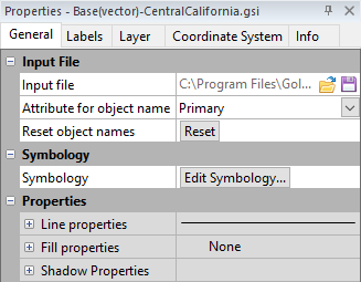
The General page in the base map properties contains options for setting feature properties. The properties can be applied based on attribute values, or properties can be the same for all objects within the layer.
The base map properties General page contains the following options:
|
|
|
The General page specifies the Input file, Symbology, and shared properties. |
Input File
The Input File lists the current file used in the base map.
Change File
Click the  button to display the Import dialog. This allows you to select a new file or an updated version of the current file used to create the base map. If the file exceeds the current map limits, you will be prompted to adjust the map limits.
A vector file must be selected when changing the Input file for a base (vector) layer. An error message will be displayed if a raster file is selected in the Import dialog. If you wish to add an image to the map, select the Home | Add to Map | Layer | Base command instead.
Coordinate System Note
Regardless of the file selected with either the Map Tools | Reload | Map Data command or by clicking the button in the Properties window, the coordinate system for the original map layer is used after updating the file. If this is not the correct coordinate system, click on the map layer to select it. In the Properties window, click on the Coordinate System tab and set the coordinate system to the appropriate new system.
Save File
The  button displays the Export dialog. Type a File name and change the Save as type to the desired file format. Click Save. For some file types, a file type specific Export Options dialog appears. The Export Options dialog Spatial References and Scaling pages are available when saving a base layer. Check the desired file formats. It is recommended that GS Reference (Version 2) file option be checked to generate a .GSR2 file. Set any export options and click OK to save the file.
Attribute for Object Name
The Attribute for object name shows the attribute field from the Attribute Table. The default is None. The names shown in the Contents window for the objects in the base layer correspond with their attribute value from the attribute field selected. Objects without attribute values are named according to their object type, e.g. Polygon. All objects are named according to their object type when None is selected. Changes made to the object's attribute value in the attribute table will be shown in the object's name in the Contents window when the attribute field is selected. Changing an object name in the Contents window using Rename Object does not change the object's attribute value.
Reset Object Names
To reset all custom object names, click the Reset button to return the object names to their attribute values.
Symbology
Symbology uses symbols or colors to display statistical information about the features in the base layer. Symbology applies line, fill, and/or symbol properties to features in the base layer depending on an attribute value. The type of symbology and the layer's appearance are controlled in the Symbology dialog. Click Edit Symbology in the Base (vector) layer Properties window General page to open the Symbology dialog. These are the symbology types in Surfer:
- Unique Values - Line, fill, and/or symbol properties are specified for unique values in the attribute field.
- Unclassed Colors - Colors from a color spectrum are applied to the features by numeric attribute value.
- Unclassed Symbols - Symbols are added for each polygon feature and scaled proportionally by numeric attribute value, or point features are scaled by numeric attribute value. Unclassed Symbols symbology is not applied to polylines.
- Classed Colors - Colors are applied to the features by classifying numeric attribute values.
- Classed Symbols - Symbols are added for each polygon feature and classified by a numeric attribute value, or point features are classified by a numeric attribute value. Classed Symbols symbology is not applied to polylines.
- Pie Chart - Attributes in the base layer are added as Pie Chart symbols with classified pie slices.
None can also be selected. When symbology is not used, the properties are controlled for all features in the Properties section of the General page for the base layer or controlled for individual features in the Line, Fill and/or Symbol Properties window pages.
Properties
The Properties section controls the properties for all objects in the base layer when no symbology is applied. When Symbology is applied to the objects, the Properties section controls the properties for any object not included in the symbology and for properties of the objects that are not determined by the Symbology settings. For example, when Unclassed Colors is used for polygon features the polygon fill properties are controlled by the symbology and the polygon line properties are controlled in the Properties section.
The Properties section is separated by property type:
- Click the
 next to Line Properties to adjust the line properties for all objects in the base layer.
 - Click the next to Fill Properties to adjust the fill properties for all objects in the base layer.
- Click the next to Font Properties to adjust the font properties for all objects in the base layer.
- Click the next to Symbol Properties to adjust the symbol properties for all objects in the base layer.
- Click the next to Shadow Properties to adjust the shadow properties for all objects in the base layer.
If no object exists in the base layer that uses a particular property type, that property type is not displayed.
See Also
General Page - Base (raster) Layer
Assigning Coordinates to a Base (raster) Layer