Viewshed
A Viewshed layer performs a visibility analysis on an underlying grid file, indicating which specific cells are directly visible from a designated observer or transmitter position. Viewshed layers can be generated as a brand-new standalone map or added as an overlay to an existing map object.
|
|
|
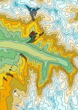
In this viewshed example, areas that are visible from the transmitter location are indicated with the partially transparent black fill. |
On this page:
- Creating a New Viewshed Map
- Adding a Viewshed Layer to an Existing Map
- Strict Map Object Requirements
- Setting Map tilt to 90°
- Overlay Creation Steps
- Interactive Tool Mode Mechanics
- Viewshed Properties
- Map Properties
Creating a New Viewshed Map
You can generate a brand-new map object directly from a viewshed layer. This command processes exactly like any other standard grid-based map type:
-
Click the Home | Create Layer | Specialty | Viewshed command.
-
In the Open Grid(s) dialog box, select a valid grid file and click Open.
Note: The selected grid file must not be planar; a non-planar grid containing elevation variance is required to perform the line-of-sight visibility analysis. Upon generation, the transmitter position is automatically placed in the dead center of the grid extent by default.
Adding a Viewshed Layer to an Existing Map
Viewsheds can only be created when the Map View Tilt is 90, the Map View Projection is set to Orthographic, and the map does not contain a layer. If the map does not meet these settings, the Viewshed command will be grayed out. If your map does meet the requirements, follow the instructions below to add a Viewshed layer. Viewsheds cannot be added to Wireframe maps.
-
Select the map you want to add a viewshed layer to.
-
Click the Home | Create Layer | Specialty | Viewshed command.
-
In the Open Grid(s) dialog box, select a valid grid file and click Open.
Strict Map Object Requirements
A viewshed overlay can only be safely introduced if the target map matches specific orientation rules. An explicit error message will prevent generation if the destination map contains any of the following settings:
-
The Map View Tilt is set to any value other than 90 degrees.
-
The Map View Projection is configured for Perspective projection instead of Orthographic.
-
The map group contains a Wireframe map layer.
Setting Map tilt to 90°
Viewsheds can only be added to maps that are not tilted and in the orthographic projection. To temporarily change a Surface map to this orientation:
- Click on the Map object in the Contents window.
- In the Properties window, click on the View tab.
- Change the Projection to Orthographic.
- Click and drag the Tilt (degrees)
 to 90.
 - Then, click the Home | Create Layer | Specialty | Viewshed command.
Once the viewshed is located on the map, the Projection and Tilt (degrees) can be changed back to their previous values.
Overlay Creation Steps
-
In the Contents window, click on the existing map object that contains a 2D grid layer, i.e., contour, color relief, Vector (1-Grid), Vector (2-Grid), or watershed map.
-
Click the Home | Create Layer | Specialty | Viewshed command.
-
In the Open Grid(s) dialog box, select a valid grid file and click Open.
Interactive Tool Mode Mechanics
When entering an interactive tool mode to place a new viewshed or to repick its coordinates, the following system mechanics govern the environment:
-
If you click on, alter, or select an entirely different object workspace mid-operation, or if you change or delete the selected viewshed, Surfer terminates the placement tool and returns automatically to standard Select mode.
-
Pressing the ESC key on your keyboard cancels placement and drops Surfer back into standard Select mode.
-
No other keyboard inputs or keys will trigger an active function while this specific placement mode is open.
-
Full Undo/Redo support tracks all placement and coordinate adjustments flawlessly.
Boundary Tracking Rule: If you click or attempt to manually adjust the transmitter coordinates completely outside the geographic limits of the underlying grid file, an error message will display utilizing strict "transmitter position" terminology to identify the boundary truncation. You can refine the exact position numerical properties inside the Property Manager at any time.
Viewshed Properties
Once created, a viewshed layer can be fully customized by selecting it within the Contents window and altering parameters within the Properties window. Properties are organized across the following sub-pages:
-
General: Contains parameters for visibility sweeps, target elevations, and transmitter position tracking. Under the Transmitter Position section, the following updated options are now available:
-
Position: Displays the current coordinates as a unified text string row value. Manually updating the individual X and Y property fields dynamically updates this combined value field automatically.
-
Pick new transmitter position: Clicking this button enters an interactive tool mode featuring custom help text and a dedicated icon, allowing you to click anywhere directly onto the map canvas to visually update the transmitter coordinates.
-
-
Layer: Handles opacity and blending.
-
Coordinate System: Manages the layer projection coordinate systems.
-
Info (Grids): Displays structural grid file metrics.
Map Properties
The map properties contains the following pages: