Assign NoData
The Grids | Edit | Assign NoData command is used to remove grid node data from a grid in areas not supported by original data or in areas where you do not want to display the map. The Assign NoData command assigns the NoData value (1.70141e+038) to specified groups of grid nodes in a grid file. Grids with Assign NoData applied contain the same number of grid nodes and the same grid limits as the original grid file. The grid nodes in the new grid are identical to the values in the original grid except in those locations where the NoData values are assigned.
NoData polygon boundaries are defined in a vector file or in a base layer. The blanking file format can be used and is a special ASCII format file containing the X, Y coordinates defining the NoData polygon boundary. Blanking *.BLN files can be created in the Surfer worksheet, with the Digitize command, or by exporting a vector base layer. The NoData values can be assigned to areas inside or outside the polygon or 3D polygon boundary. Regions can also be assigned the NoData value using the Eraser command in the Grid Editor window.
Nearly any feature type can be used when specifying boundaries with a base layer: polygon, range ring, rectangle, rounded rectangle, or ellipse. A polyline or spline polyline can also be used, but unexpected behavior may occur if the line is open. The most common feature for defining NoData polygon boundaries is the polygon or 3D polygon. The features must be in a base layer to be used with the Assign NoData command. Features in paper space cannot be used. Create new features in an empty base layer if you wish to assign NoData values with features created in Surfer.
To automatically assign the NoData value to areas outside the original data, click the Grids | New Grid | Grid Data command. In the Grid Data dialog, select 2D convex hull or Alpha shape in the Assign NoData outside of field. Any grid nodes outside the boundary created by connecting the original data is automatically assigned the NoData value.
In Surfer 14 and prior versions, the Assign NoData command was referred to as Grid Blank.
Assign NoData to Grid Dialog
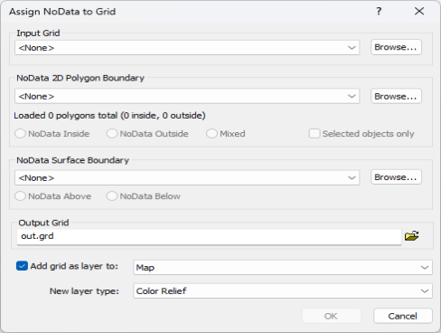
The Assign NoData to Grid dialog is displayed by clicking the Grids | Edit | Assign NoData command or the  button. Specify the input grid layer or file, vector file or layer, output grid file, and optional output map layer in the Assign NoData to Grid dialog.
|
|
|
Assign the NoData value to regions of a grid file or map layer with the Assign NoData to Grid dialog. |
Input Grid
Specify the source map layer or grid file in the Input Grid section. Click the current selection and select a map layer from the list. Only map layers created from grid files are included in the Input Grid list. Click Browse to load a grid file with the Open Grid dialog.
NoData 2D Polygon Boundary
Specify the region or regions to be assigned the NoData value and whether or not to use only selected objects in the NoData 2D Polygon Boundary section. Select either a map layer or vector file in the NoData 2D Polygon Boundary section:
-
Click the current selection and select a base layer from the list. Only base layers that contain at least one eligible polygon or polyline will be included in the list. The base layer must use the same source coordinate system as the grid.
-
Click Browse to load a vector file with the Open dialog. The file must use the same coordinate system as the grid.
The number of polygons and vertices is displayed below the NoData 2D polygon boundary once a file or map layer has been selected. If the boundaries have blanking flags or BLN_Flag attributes, the total number of inside and outside flags is displayed.
Note that all boundaries are treated as 2D polygon boundaries when assigning NoData meaning that only the XY coordinates are used when determining which grid nodes will be assigned the NoData value. For 3D grids, this means that the same XY boundary will be used to assign NoData at all Z levels.
Polyline Boundaries
2D and 3D polylines can be used for NoData polygon boundaries. The polylines in the base layer or vector file will be treated as polygons and 3D polylines treated as 3D polygons while assigning NoData values. The Assign NoData command is not recommended with open polylines as unexpected results may occur. Before clicking Grids | Edit | Assign NoData, consider converting the object to another type better suited to the operation you wish to perform with one of the Change To commands, and edit features with the Reshape command.
If the layer you wish to use contains both polygons and polylines, but you only wish to use some or all of the polygons, select the objects you wish to use before clicking Grids | Edit | Assign NoData and select the Selected objects only option. If the file you wish to use contains both polylines and polygons, first load the file as a base layer, and then use the Assign NoData command with the Selected objects only option.
Inside, Outside, or Mixed
Select Inside to assign the NoData value to the region inside the NoData polygon/3D polygon boundary or boundaries. Select Outside to assign the NoData value to the region outside the NoData polygon/3D polygon boundary or boundaries. Select Mixed to use the blanking flag or BLN_Flag attribute values from the file or layer. The Mixed option is only available when the layer or file contains both blanking flags or BLN_Flag attributes: assign NoData inside (1) and assign NoData outside (0). If all blanking flags or BLN_Flag attributes are the same, the NoData Inside or NoData Outside option is selected automatically, and the Mixed option is not available.
Selected Objects Only
Select the Selected objects only option to use only the selected objects in the base layer to assign NoData values to the grid. When the Selected objects only box is checked, the Loaded polygonsandvertices values are updated. Select a base layer in the NoData 2D Polygon Boundary field to use the Selected objects only option. The Selected objects only option is not available when the NoData 2D Polygon Boundary is a vector file. The polygon or polygons must be selected before clicking the Grids | Edit | Assign NoData command.
Supported Vector Formats
The following file formats can be used to assign NoData values to a grid based on a polygon boundary:
NoData Surface Boundary
Specify the region or regions to be assigned the NoData value based on whether they sit above or below a surface in the NoData Surface Boundary section. Select either a map layer or 2D grid file in the NoData Surface Boundary section:
-
Click the current selection and select a grid based layer from the list. Only layers created using a supported 2D grid file format will be included in the list. The layer must use the same source coordinate system as the input grid.
-
Click Browse to load a grid file with the Open dialog. The file must use the same coordinate system as the input grid.
NoData Above or Below
Select NoData Above to assign the NoData value to the region above the NoData surface boundary or boundaries. Select NoDataBelow to assign the NoData value to the region below the NoData surface boundary or boundaries.
Output Grid
In the Output Grid group click the ![]() button to open the Save Grid As dialog. Specify a path or file name for the grid file to be created and click Save. A variety of output grid file types can be specified. Alternatively, type a file path and name, including the file type extension, in the Output Grid field.
button to open the Save Grid As dialog. Specify a path or file name for the grid file to be created and click Save. A variety of output grid file types can be specified. Alternatively, type a file path and name, including the file type extension, in the Output Grid field.
Add New Map or Layer
Check the Add grid as layer to check box to automatically add the created grid to a new or existing map. Select [New Map] in the Add grid as layer to field to create a new map. Click the current selection and select an existing map to add a new layer to the map. Select the layer type by clicking the current selection in the New layer type field and selecting the desired layer type from the list.
Assign NoData Example
In this example, some of the nodes in the Demogrid.grd sample file will be assigned the NoData value with the Demorect.bln sample file.
- Click the Home | New Map | Contour command.
- In the Open Grid dialog, select the Demogrid.grd sample file and click Open.
- Click on the contour map in the plot window.
- Click the Home | Add to Map | Layer | Base command.
- In the Import dialog, select the DemoRect.bln sample file and click Open .
- In the plot window, click the Grids | Edit | Assign NoData command.
- In the Assign NoData to Grid dialog, click <None> in the Input Grid field and select Contours-Demogrid.grd from the list.
- Click <None> in the NoData Polygon Boundary field and select Base-DemoRect.bln from the list.
- Click the button next to NoData Outside.
- Specify a file name and path in the Output Grid field.
- Verify the Add grid as layer to check box is checked.
- Verify [New Map] is displayed in the Add grid as layer to field.
- Click the current selection in the New layer type field and select Contour.
- Click OK in the Assign NoData to Grid dialog.
A new grid is created and saved to the file name specified in step 10. A new contour map is created and displayed in the plot window.
|
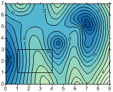
Before Assign NoData: |
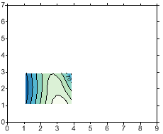
After Assign NoData: |
||
|
|
||
|
The Blanking *.BLN file is displayed as a base map layer on the contour map. |
This is a contour map created from the new grid file. |
If the edges of the NoData region are jagged, the original grid file can be recreated with a higher grid density (i.e. more rows and columns). Use the more dense grid file and follow the steps to assign the NoData values to the grid file again. Assigning NoData values marks areas of a grid or map as "no data" areas. In NoData areas of a grid:
- Contours are not drawn.
- A separate fill color can be assigned to NoData regions/missing data in contour maps and color relief maps.
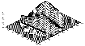
- 3D wireframe maps display a flat surface at the minimum Z value in the grid file.
- Volumes are not calculated and areas are calculated separately.
- Grids | Calculate | Math operations produce a NoData node if one of the grids contains a NoData node at a given location, unless a Remap to is selected for the grid.
Example 2
|
|
|
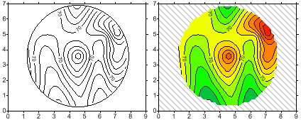
The left map shows an unfilled contour map with a base map layer displaying the circular NoData polygon boundary. Contour lines are truncated within one grid cell width of the boundary. The right map shows a filled contour map with a forward slash fill pattern assigned to NoData areas. |
|
|
|
NoData regions appear as low flat regions on a 3D wireframe. This wireframe is produced from the same grid file used to produce the contour maps in the example above . |
Assigning NoData to Areas within a Grid
There are several ways to assign the NoData value to areas within a grid.
Starting with a data file, the Grids | New Grid | Grid Data command assigns the NoData value to grid nodes:
- where the search criteria are not satisfied.
- outside the convex boundary of the data set if the triangulation or natural neighbor gridding methods are used.
- outside the convex boundary of the data set with any gridding method if the Assign NoData grid outside 2D convex hull of data option is checked.
- within an area delineated by a fault polygon if there are no data values within that area.
Starting with a grid file, nodes are assigned NoData if:
- the Grids | Edit | Assign NoData command is used to assign NoData values to the area inside or outside a boundary defined by a blanking file or base layer.
- the Eraser tool is used to assign NoData values to grid nodes in the grid editor.
- the Grids | Edit | Filter is used to assign NoData values to filtered grid nodes.
Assign NoData and .GSR2 Files
When the input .GRD file for a Grids | Edit | Assign NoData command has a defined .GSR2 file with coordinate system information, this information is used for the output .GRD file. The .BLN file must be in the same coordinate system as the input .GRD file, otherwise the file is not assigned the NoData value. The Export Options dialog appears with the option to save the coordinate system information. It is recommended to check the GS Reference (Version 2) file if you intend to use the grid file in Surfer, as the GSR2 retains all of the information needed. The grid has the same coordinate system as the original file, but the .GSR2 is required to define the coordinate system.
